Automatic inspection of printing plates or cylinders

Inactive Publication Date: 2000-02-29
CREO IL
View PDF8 Cites 22 Cited by
  • Summary
  • Abstract
  • Description
  • Claims
  • Application Information

AI Technical Summary

Benefits of technology

The present invention provides a novel method for inspection of a surface of a printing medium, e.g. a printing plate or gravure cylinder. In accordance with the present invention an image of the printing surface is optically acquired, a real digital representation of the surface is produced and a computer then determines whether the real digital representation has a defect or not and provides an o

Problems solved by technology

The formation of the printing plate for offset printing or the cylinder for gravure printing, is error prone and very often defects occur.
Such errors may arise from a number of sources.
If air pockets (or dust particles) remain between the film and the plate, the exposed image will have non-uniform areas.
In addition, errors in plate exposure may be caused by scratches, dust and paper/cloth lint that remain on the film after cleaning.
However, errors in imaged areas and errors related to separation or imposition order cannot be corrected at all.
One source of defects in the manufacturing process of gravure cylinders is faults which occasionally occur in the stylus, e.g. a chopped tip, stylus rib defects and others which may be caused, for example, by stylus material fatigue, rib wearing, etc.
In addition, abnormal gravure cells are formed at times by inaccuracies in the current which drives

Method used


Image

  • Automatic inspection of printing plates or cylinders
  • Automatic inspection of printing plates or cylinders
  • Automatic inspection of printing plates or cylinders

Examples


Embodiment Construction

Before describing some embodiments of the present invention in detail, two specific, non-limiting examples of a system useful in the performance of the method of the present invention will be described, one useful in the manufacture of offset plates and the other in the manufacture of gravure cylinders.

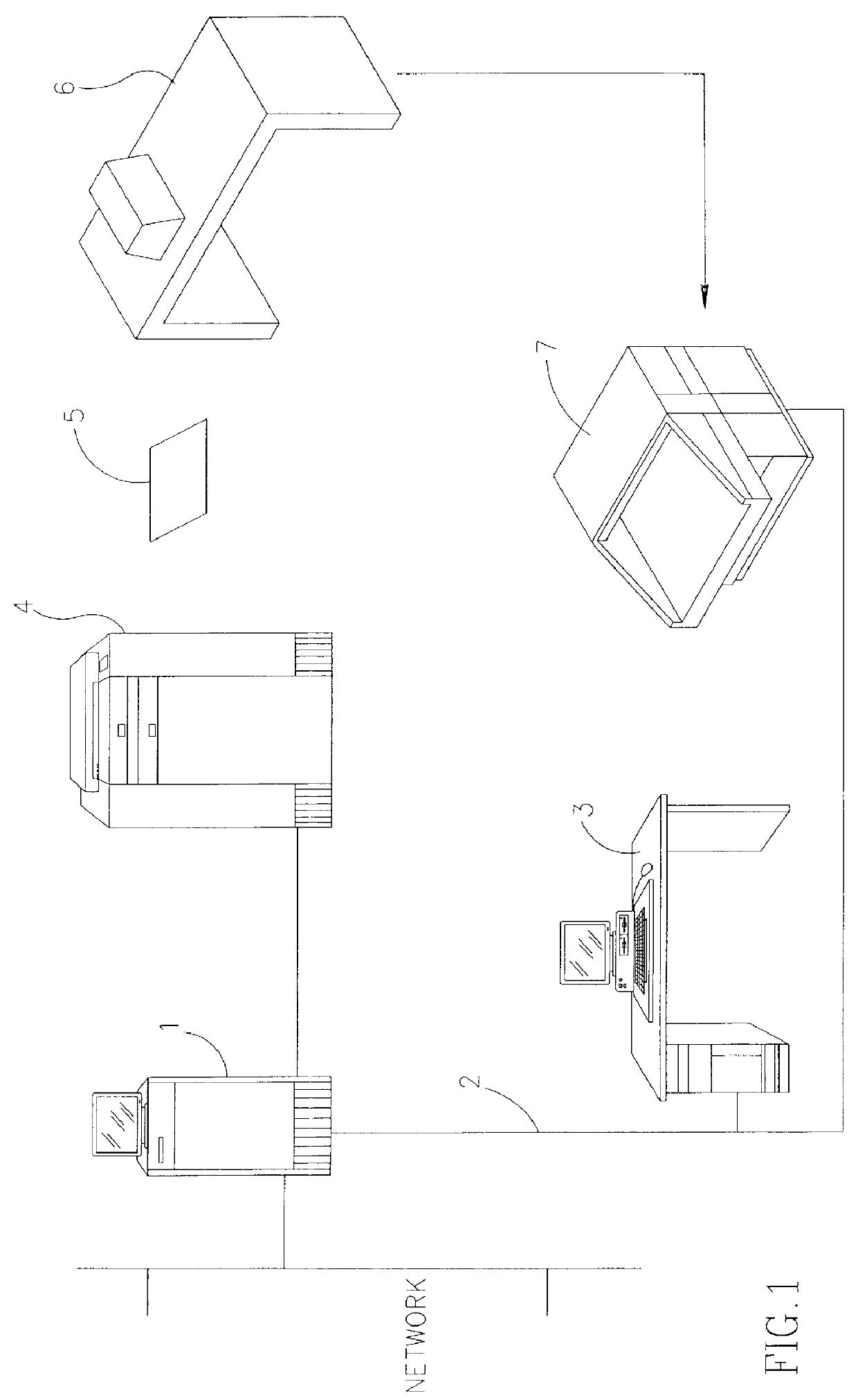
Attention is directed to FIG. 1 showing a schematic illustration of a system useful in an embodiment of the invention which serves for the manufacturing of offset plates. The system comprises a computer 1 such as micro-Whisper / I.TM. computer, commercially available from Scitex Corporation, Herzlia, Israel, interlinked by means of communication network 2 to workstation 3 such as a Prisma.TM. or Star PS.TM., commercially available from Scitex Corporation, Herzlia, Israel. Computer 1 is also linked to image setter 4 such as Dolev 200.TM. commercially available from Scitex Corporation, Herzlia, Israel.

In operation, a reference digital representation of an imposed printing plate, which is ...


PUM


Abstract

A method for inspecting a surface of a printing medium, the method comprising the steps of acquiring an image of the surface or a portion thereof, digitizing the acquired image whereby a digitized real representation of the surface or portion is obtained. The method also include the step of for each of said digitized real representation performing either or both of the steps of comparing said digitized real representation with a digital reference representation, said reference representation being a virtual digital fault-free representation of said surface or portion thereof and determining whether said real digitized representation is in compliance with stipulations of a set of rules which define the characteristics of a fault-free digital representation of said surface or portion, and providing either a correct indication output signal where there is a match between said real digitized representation with said reference digital representation in the case of the step of comparing or compliance with said rules in the case of said step of determining, or fault indication output signal where there is a mismatch in the case of the step of comparing or incompliance in the case of the case of determining.

Description

The present invention relates to a method and system for the inspection of a printing plate or cylinder, in order to automatically detect errors and defects which may influence the quality of the print.Books, magazines and other publications are typically produced by offset or gravure printing. In offset printing, a plate is imaged in a contact frame or by direct exposure to a laser beam. The plate is later mounted on a press and then impressed on the printed substrate. In gravure printing, a cylinder is engraved by laser exposure and subsequent chemical etching or by the use of a penetrating pyramid shaped diamond stylus in an apparatus known as a "helioklischograph".The formation of the printing plate for offset printing or the cylinder for gravure printing, is error prone and very often defects occur. Such errors may arise from a number of sources. In offset printing the plates are routinely imaged in vacuum contact frames or Step and Repeat machines such as Impomaster.TM. (manuf...

Claims


Application Information

Patent Timeline
IPC IPC(8): B41F33/00
CPCB41F33/0027B41F33/0036B41N3/003
Inventor BRONSTEIN, RAFAILKARP, OMERGOLDSTEIN, MICHAEL
Owner CREO IL
Why Eureka
Try Eureka