Cyclonic dust collector

a dust collector and cyclonic technology, applied in the direction of gas current separation, centrifuges, separation processes, etc., can solve the problems of difficult indoor placement of traditional dust collectors, large volume of air laden with dust and debris, and large volume of air containing dust and debris

Inactive Publication Date: 2000-03-07
PELLETRON CORP
View PDF6 Cites 23 Cited by
  • Summary
  • Abstract
  • Description
  • Claims
  • Application Information

AI Technical Summary

Problems solved by technology

However, this process, while cleaning the product, results in the creation of a volume of air heavily laden with dust an debris, much of which is extremely small in size.
A traditional dust collector would be difficult ...

Method used


Image

  • Cyclonic dust collector
  • Cyclonic dust collector
  • Cyclonic dust collector

Examples


Embodiment Construction

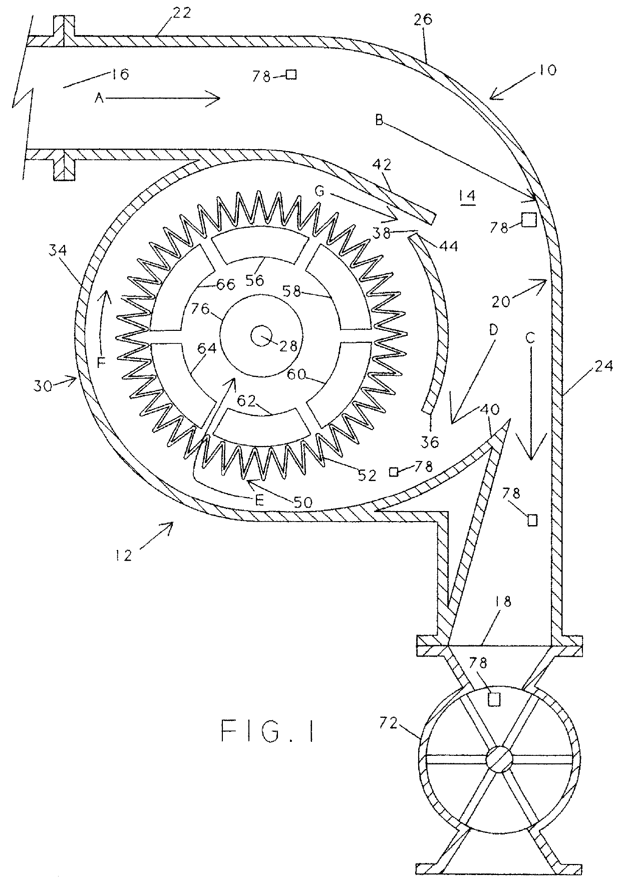
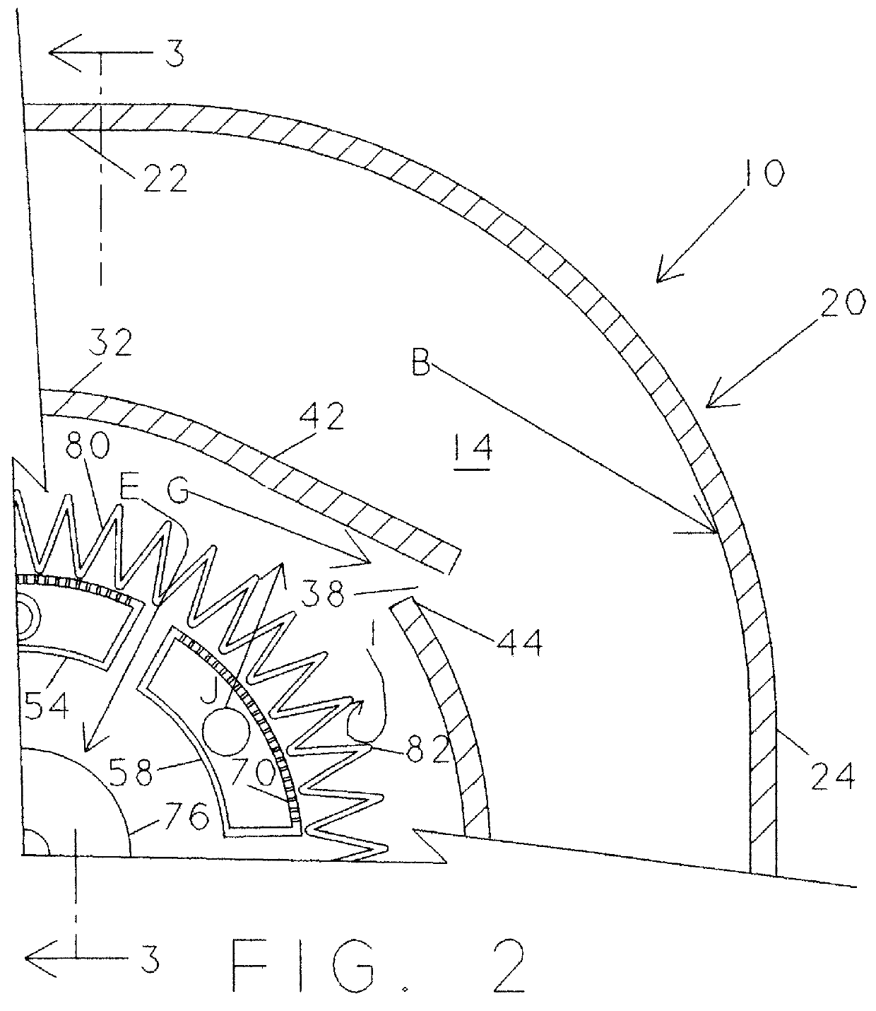
Turning now to the figures, the subject cyclonic dust collector 10 is formed by a housing 12 defining a cyclone chamber 14 having a substantially horizontal inlet 16 and a substantially vertical dust outlet 18. The chamber 14 is formed by outer wall 20 which comprises a horizontal section 22, a vertical section 24, and an intermediate smooth curved surface of transition 26 extending about 90.degree., in the down stream direction from the vertical, about an axis 28. The inner wall 30 of the chamber 14 has a horizontal portion 32 connected tangentially to a partial cylindrical inner wall 34 extending about 120.degree., in the down stream direction from the vertical, about axis 28 to an edge 36. The inner wall 34 is broken by a reflux venturi slot 38 and an intake wall 40. The reflux venturi slot 38 is formed by a tangential plate 42 overlying and spaced from a lip 44. The reflux venturi slot 38 is preferably located between 15.degree. and 45.degree. from the vertical in the down strea...


PUM

PropertyMeasurementUnit
Timeaaaaaaaaaa
Timeaaaaaaaaaa
Pressureaaaaaaaaaa

Abstract

A method and apparatus for collecting and removing dust from dust laden air has a housing defining a chamber having an inlet for the dust laden air, a first outlet for dust free air and a second outlet for the collected dust, the inlet and second outlet being connected by a curved wall. A filter cartridge is mounted in the chamber at the axis of the curved wall and is at least partially enclosed within and inner wall which, together with the outer wall forms a cyclonic passage for the air passing therethrough. High velocity air flow is directed into the chamber wherein at least some of the dust will strike the chamber wall at high velocity causing a rapid change in kinetic energy and detraining the dust from the air, this dust then falling from the air stream and removed from the chamber through an air lock or similar device. The air then revolves around and is drawn through the filter removing the remaining dust therefrom. Periodically, bursts of reverse flow air are sent through segments of the filter to cause dust lodged therein to be reentrained in the flowing air and carried to the dust exit.

Description

1. The Field of the InventionThe present invention relates to a method and apparatus for removing dust entrained in an air stream and, in particular, to a method and apparatus utilizing a unique cyclonic air flow, coupled with an improved filter assembly, to remove substantially all particles from the air stream while achieving long filter life, great savings in space and reduced capital and maintenance costs.2. The Prior ArtThe present invention is a dust collector of the type which can most advantageously be used with devices which use air flows to remove dust and debris from product, such as the deduster devices described in my U.S. Pat. Nos. 4,299,693 and 4,631,124, the disclosures of which are incorporated herein by reference. My earlier devices employ gravity to feed the dust and impurity laden particulate material through a linear kinetic energy cell, which cell generates an electric field to neutralize the static electrical charges, which is what causes the dust to adhere to...

Claims


Application Information

Patent Timeline
IPC IPC(8): B01D45/12B01D46/04B01D50/00B01D46/00B01D46/24B01D46/48B01D46/52
CPCB01D45/12B01D46/0046B01D46/0068B01D46/2411B01D46/4281B01D46/48B01D46/521B01D50/002B01D46/71B01D50/20
Inventor PAULSON, JEROME I
Owner PELLETRON CORP
Why Eureka
Try Eureka