Gas sensor with protective gate, method of forming the sensor, and method of sensing

a technology of gas sensors and protective gates, applied in the field of gas and vapor sensors, can solve the problems of corrosive environment, high maintenance cost, and very powerful instruments

Inactive Publication Date: 2000-03-28
GENERAL ELECTRIC CO
View PDF18 Cites 57 Cited by
  • Summary
  • Abstract
  • Description
  • Claims
  • Application Information

AI Technical Summary

Problems solved by technology

These instruments are very powerful, but they have significant disadvantages, such as being very maintenance intensive.
Further, these instruments are sensitive to adverse, corrosive environments and must be located far from the gas or vapor source in a climate controlled enclosure.
Thus, a gas (vapor) sample must be transported to the analyzer, as a result real time information is not available.
Also, these instruments are expensive, and are thus not affordable candidates for real-time, in-situ applications.
Further, within these very few sensors there are even fewer that are relatively reliable to accurately detect individual gases.
For example, an unreliable sensor does not provide correct indication of a gas amount when the concentration of an interferant is high.
This solution, however, limits the effectiveness and uses of a sensor.
Faults in an oil-filled transformer include arcing (electrical), corona discharge (electrical), low energy sparking (electrical), severe overloading (electrical), pump motor failure (electrical and thermal) and overheating (electrical and thermal) in an insulation system.
These fault conditions result in a transformer malfunctioning or indicate an impending malfunction, which, if not corrected, may lead to failure of the transformer.
Accordingly, while an individual sensor may be useful to detect a single gas to which it is tuned, it will not be as useful to detect other gases.
If the sensor is not appropriately tuned, the designated gas may not accurately detected, which of course is undesirable.
Further, known sensors do not provide protection of the sensor components from harmful environments.
For example, corrosive gases are often present in a transformer, and adversely affect operation of a sensor.
Also, these known sensors are not protected from water or particulate foreign matter interference, which are often found in transformers.
However, these proposals are not seen to protect the sensor from corrosion, water and foreign particulate materials.

Method used


Image

  • Gas sensor with protective gate, method of forming the sensor, and method of sensing
  • Gas sensor with protective gate, method of forming the sensor, and method of sensing

Examples


Embodiment Construction

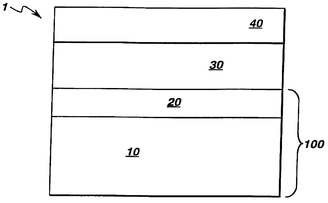
Gas sensors, such as, but not limited to, a metal-insulator-semiconductor (MIS) diode gas sensor and a field effect transducer (FET) gas sensor, are known in the art. The sensors comprise a semiconductor substrate; a thin insulator layer mounted on the semiconductor substrate; and a catalytic metallic gate (gate) mounted on the thin insulator layer. These known sensors have been generally used for monitoring gas in clean, dry, noncorrosive environments.

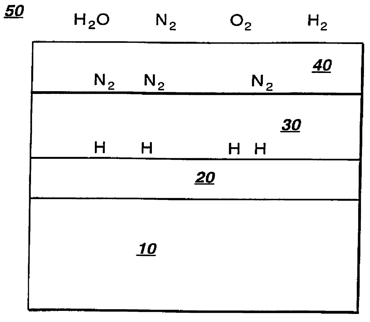
A generalized operation of an MIS gas sensor will now be provided, using hydrogen gas as the detected gas. The sensor, its operation and the hydrogen gas are merely exemplary, and are not meant to limit the invention. Initially, hydrogen gas molecules (H.sub.2) are adsorbed onto the metallic gate from the surrounding ambient environment. The adsorbed molecules are altered, such as by being catalytically dissociated from each other on one of a molecular or atomic level. For hydrogen gas (H.sub.2), the molecules (H.sub.2) are dissociate...


PUM

PropertyMeasurementUnit
thicknessaaaaaaaaaa
thicknessaaaaaaaaaa
thicknessaaaaaaaaaa

Abstract

A gas sensor determines the presence of at least one designated gas in a gaseous environment. The gas sensor comprises a semiconductor substrate; a thin insulator layer disposed on the semiconductor substrate; a catalytic metallic gate disposed on the thin insulator layer; and a chemically modified layer disposed on the catalytic metal gate. The chemically modified layer comprises a material that protects the sensor from corrosive gases and interference from at least one foreign matter and water, alters at least one of surface chemical properties and surface physical properties of the sensor, and passes only the designated gas therethrough.

Description

The invention is related to gas sensors. In particular, the invention is related to a gas sensor with a protective gate.DISCUSSION OF RELATED ARTGas and vapor sensors have many industrial applications. These applications include the detection of hazardous gas in the workplace for worker safety, enhanced control of the air-fuel mixture and feed in combustion of fuel, increased product yield and reduced waste in a product stream. These applications generally rely on individual sensors, which are installed to detect a single gas or vapor whose concentration may approach a harmful level. The examples of these gases include, but are not limited to, hydrogen sulfide, carbon monoxide, chlorine, ammonia, hydrogen, and methane.Methods for industrial gas and vapor sensing have evolved basically along two technology paths. The first path involves use of complex analytical instruments, for example infrared spectroscopy, gas chromatography, and mass spectrometry. The development of microcontroll...

Claims


Application Information

Patent Timeline
Patent Type & Authority Patents(United States)
IPC IPC(8): G01N27/403G01N27/414G01N27/00G01N33/26G01N33/00G01N33/28
CPCG01N33/0014G01N33/2841G01N27/4141G01N33/005
Inventor STOKES, EDWARD BRITTAINGUI, JOHN YUPENG
Owner GENERAL ELECTRIC CO
Why Eureka
Try Eureka