Continuous extrusion-compression molding process for making optical articles

Inactive Publication Date: 2000-03-28
FOREVER VISION
View PDF18 Cites 129 Cited by
  • Summary
  • Abstract
  • Description
  • Claims
  • Application Information

AI Technical Summary

Benefits of technology

to provide a thermoplastic lens molding method in which there is no down time

Problems solved by technology

This method, however, is not commercially attractive because it has a long cycle time, poor energy efficiency and it is economically less beneficial compared with an injection molding process.
In molding such optical articles as a negative powered Rx lense, however, conventional injection molding methods have a number of serious operational problems.
These type lenses have a cross section in which the center is thinner than the edge and this feature makes direct injection molding very difficult especially when the viscosity of the melt is high.
This phenomenon is especially serious when molding a lens with thinner center thickness which has higher value due to its lighter weight.
In addition, injection molding typically introduces orientation-induced stress and birefringence.
Lack of sufficient packing force used in cold runner injection molding technology often results in uneven shrinkage related lens pre-release and causes line marks on the lens surface.
Conventional injection molding has been found to be very difficult and injection-compression molding is typically used.
Even though there are different versions of the injection-compression molding technology, they are more or less similar to each other and this technology has certain drawbacks.
For one, the process often produces a product having some stress and birefringence possibly due to the large temperature difference between the mold and the melt.
Additionally, the cycle time is often very long b

Method used


Image

  • Continuous extrusion-compression molding process for making optical articles
  • Continuous extrusion-compression molding process for making optical articles
  • Continuous extrusion-compression molding process for making optical articles

Examples


example

Example of Polycarbonate Lens Molding Using Continuous Extrusion Compression Molding Method

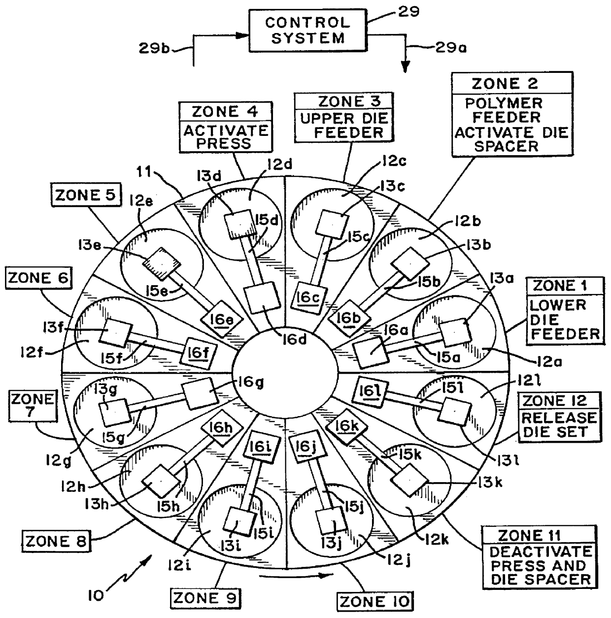
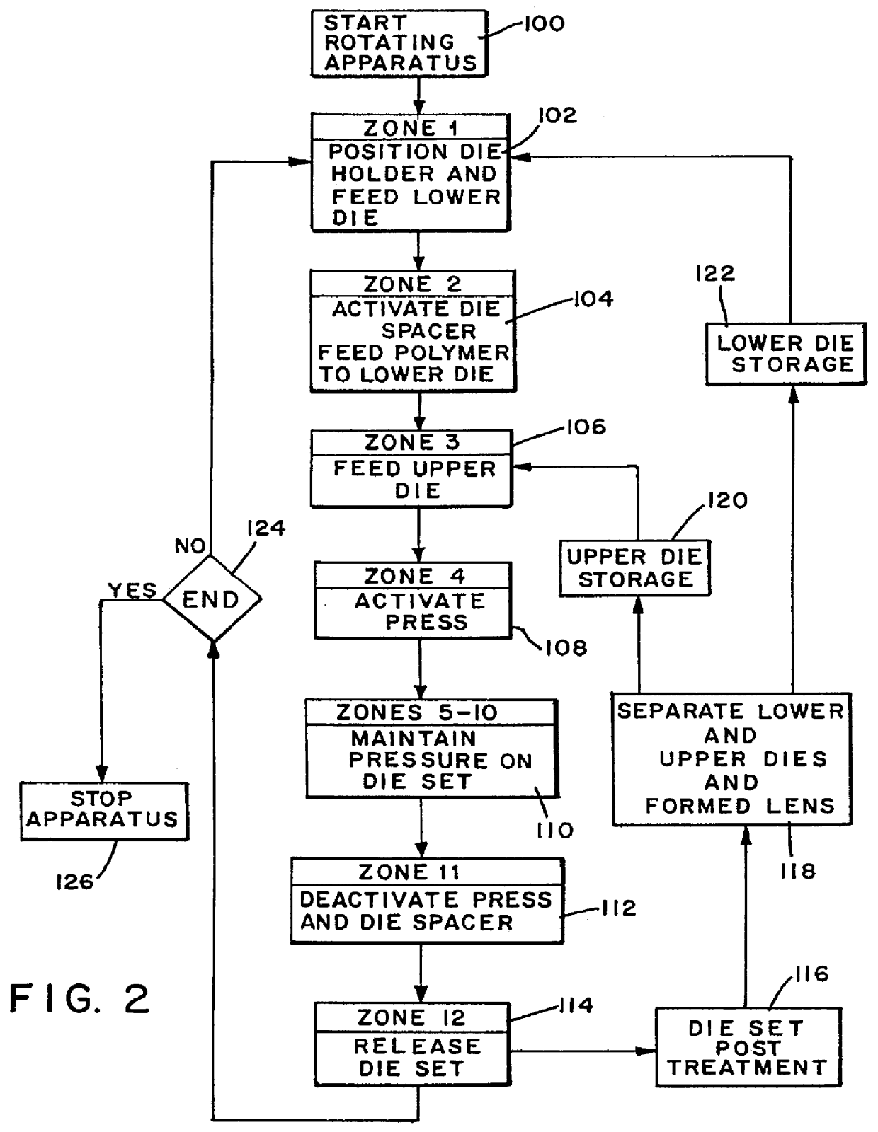
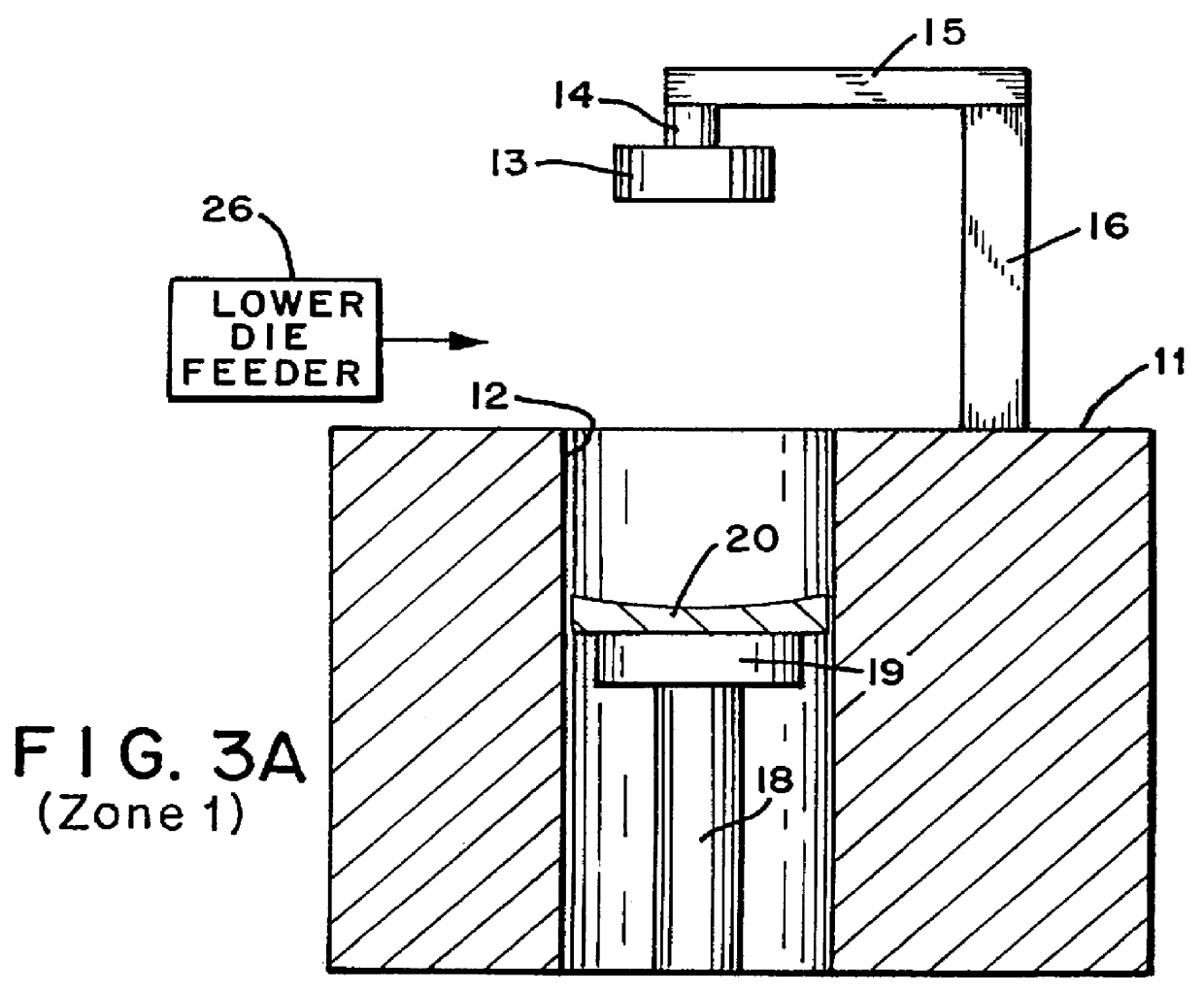
A lens article was made using a horizontal rotating turntable apparatus similar to that shown in FIG. 1. The extruder is a single screw extruder made by Merritt David Corp., L / D=24, 1.5" diameter screw, three barrel heating zones and one clamp heating zone and two sections of discharge die heating zones. Temperature settings for the zones are as follows: employed depending on the properties of the polymer and / or the requirements of the article. For example, the polymer containing die set 25 may be kept closed and the temperature of the dies maintained by heating the die set to allow annealing of the formed article therein to complete the polymerization or to eliminate any stress and birefringence without deforming the shape of the article. The polymer containing die set may also be allowed to gradually cool and then opened to release the formed article. The optical article (lens) is removed fr...


PUM

PropertyMeasurementUnit
Angleaaaaaaaaaa
Angleaaaaaaaaaa
Angleaaaaaaaaaa

Abstract

The present invention relates to making optical articles such as opthalmic lenses by molding and, in particular, to using a continuous extrusion-compression molding method to make plastic lenses whereby a polymer melt is fed from an extruder or melting apparatus to a first die of a plurality of rotating or conveyed sequentially processed compression die sets comprising a first die and a second die. The die sets are positioned on die supports on a rotating turntable or conveying system, the lenses formed by compressing the die sets with pressing means associated with each die support, the lenses separated from the dies and the dies recycled to die loading and the melt feed step of the process and the process repeated until the desired number of lenses or other optical articles such as compact disk substrates are produced.

Description

1. Field of the InventionThe present invention relates to making optical articles such as opthalmic lenses or substrates for compact disks by molding and, in particular, to using a continuous extrusion-compression molding method to make plastic lenses whereby a polymer melt is fed from an extruder or melting apparatus to a first die of a plurality of rotating sequentially processed compression die sets comprising a first die and a second die positioned on a rotating turntable or conveying system, the lenses formed by compressing the die sets, the lenses separated from the dies and the dies recycled to die loading and the melt feed step of the process and the process repeated until the desired number of lenses are produced.2. Description of Related ArtDirect compression molding of thermoplastic and thermoset polymers to make plastic optical articles such as lenses has been used for years. Basically, the compression molding process uses a packed powder or a pre-form material and the a...

Claims


Application Information

Patent Timeline
IPC IPC(8): B29C33/00B29C33/36B29C43/34B29C43/04B29C43/08B29D11/00B29C47/00B29C48/00B29C48/03
CPCB29C33/36B29C43/021B29C43/08B29C43/34B29D11/00423B29D11/00432B29C47/00B29C47/0009B29C2043/3618B29L2011/00B29L2011/0016B29L2017/003Y10S425/808B29C48/00B29C48/03
Inventor YANG, ZHOUWU, YINGHUI
Owner FOREVER VISION
Why Eureka
Try Eureka