Robot apparatus and treating apparatus

a robot and treating device technology, applied in the field of robots, can solve the problems of inability to meet the needs of patients, so as to achieve the effect of short tact time, increase in size and manufacturing cos

Inactive Publication Date: 2000-04-04
SHIBAURA MECHATRONICS CORP +1
View PDF13 Cites 80 Cited by
  • Summary
  • Abstract
  • Description
  • Claims
  • Application Information

AI Technical Summary

Benefits of technology

Accordingly, an object of the present invention is to provide a robot apparatus that can realize a short tact time without incurring an increase in size and manufacturing cost.
Another object of the present invention is to provide a treating apparatus that enables a plurality of treating apparatuses to be arranged without a useless space.

Problems solved by technology

Since the treatment chambers have to be arranged at the predetermined intervals in the circumferential direction, a useless space exists between the adjacent treatment chambers, and the entire installation space of the system is wide, accordingly.
Since this rotation requires a certain length of time, the overall tact time is inevitably long.

Method used


Image

  • Robot apparatus and treating apparatus
  • Robot apparatus and treating apparatus
  • Robot apparatus and treating apparatus

Examples


first embodiment

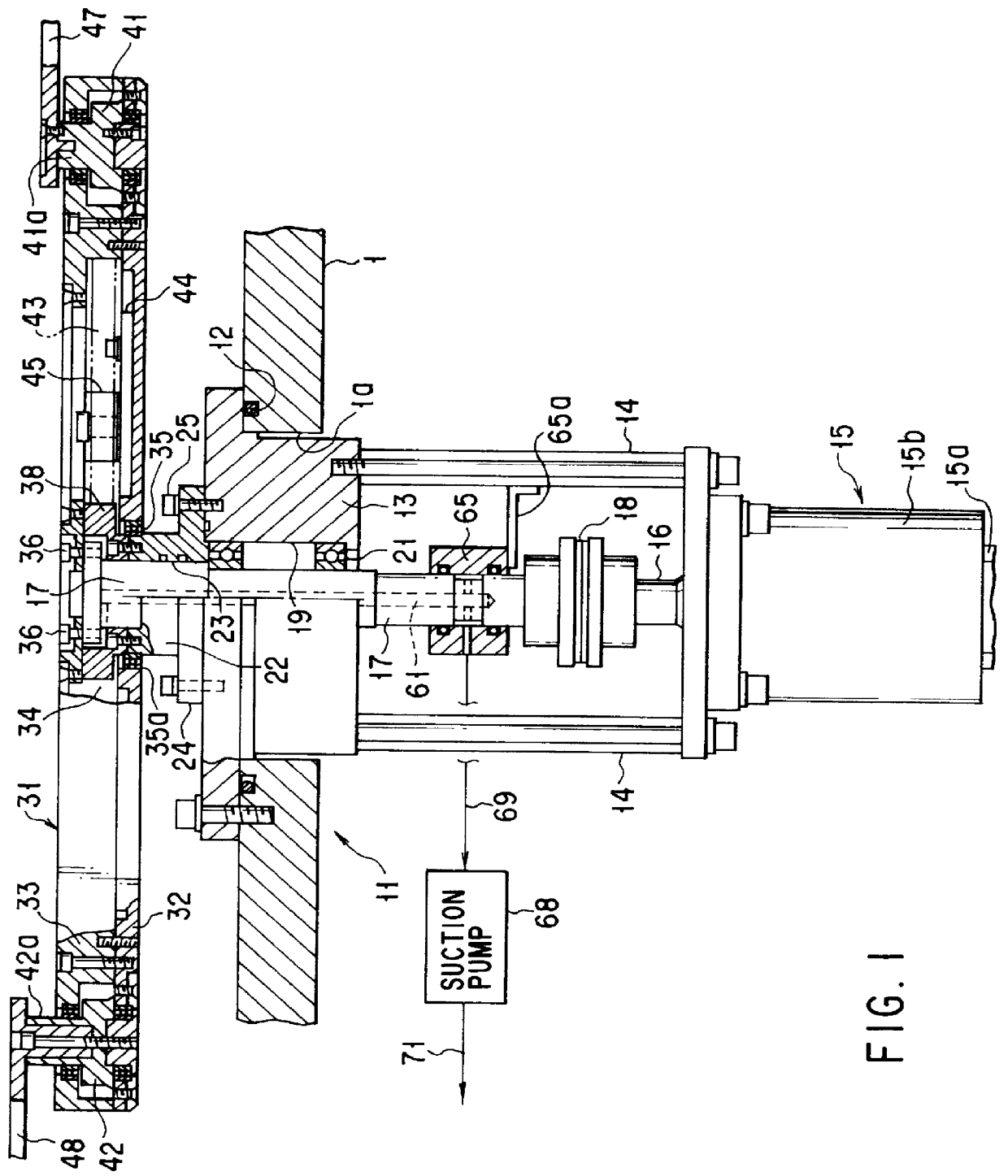
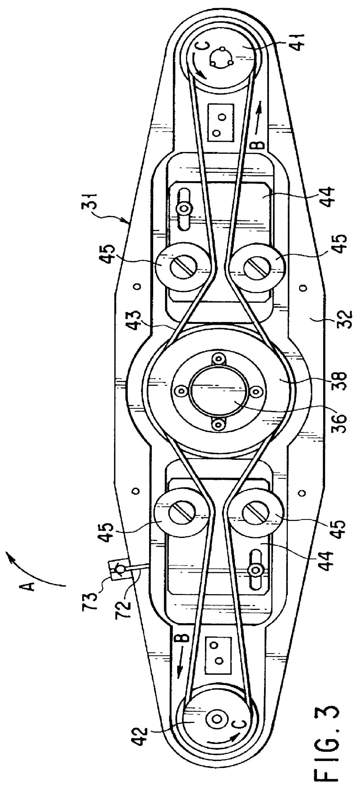
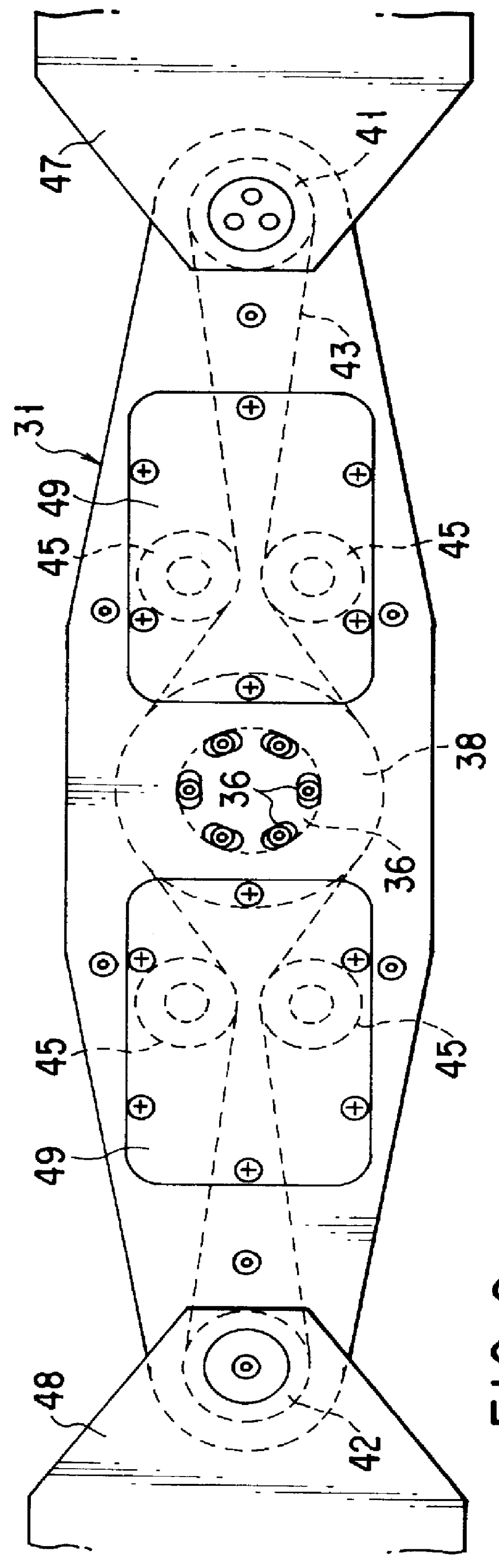
In the first embodiment, one first robot apparatus 11 is arranged between each of the treatment chambers 3a and 3b and the corresponding one of the transfer tables 5a and 5b. With this structure, the operation of transferring a semiconductor wafer U with reference to the transfer tables 5a and 5b and the operation of transferring another semiconductor wafer U with reference to the processing chambers 3a and 3b can be executed in synchronism with each other. Accordingly, the tact time can be as short as possible.

The second robot apparatus 51 is arranged between the paired transfer tables 5a and 5b, so as to transfer a semiconductor wafer U between these transfer tables 5a and 5b. With this structure, a semiconductor wafer U treated in the first treatment chamber 3a can be fed into the second treatment chamber 3b by way of the first and second transfer tables 5a and 5b. Hence, two kinds of treatments can be successively performed with respect to the semiconductor wafer.

The first embod...

second embodiment

the interlocking shaft 136 interlocks with the linear movement of the piston rod 132, the cam groove 139 described above is formed in the support member 134 that supports the interlocking shaft 136, and the cam follower 138 provided for the interlocking shaft 136 is in engagement with the cam groove 139.

With this structure, the piston rod 132 does not have to have a cam groove, as in the first embodiment. Hence, the piston rod 132 is very rigid. In addition, it is not the piston rod 132 but the interlocking shaft 136 that is rotated. In comparison with the case where the piston rod 132 is rotated, the valve body 101 can be rotated very smoothly.

FIG. 22 shows the third embodiment of the present invention. The third embodiment is directed to a modification of the structure for driving the atmospheric pressure valve 9. In FIG. 22, the same reference numerals as used in the descriptions of the first embodiment are used to represent similar structural elements, and no detailed explanatio...

fifth embodiment

FIG. 24 shows the present invention. According to the fifth embodiment, one end of an arm member 103C is coupled to the piston rod 108 of a driving means 104. The other end of the arm member 103C has a cutout spring section 151. A belt-like coupling member 152, which has a spring function, has a first projection 153a formed on one side at one end, and this projection 153a is fixedly coupled to the other end of the arm member 103C. The belt-like coupling member 152 has a second projection 153b formed on the other side at the other end, and this projection 153b is fixedly coupled to a middle portion of a valve body 101.

The valve body 101 has a dovetail groove 154 formed in that side surface which is brought into contact with a load lock chamber 7. An O-ring 102 is held in the dovetail groove 154 in such a manner that it does not come off.

The cutout spring section 151, the belt-like coupling member 152 and the valve body 101 are positioned in such a manner that their longitudinal cente...


PUM


Abstract

A robot apparatus has a rotatable arm member. A stationary pulley is arranged in the center of the arm member, while a pair of rotatable pulleys are arranged at the respective ends of the arm member. A pair of fingers, used for conveying a work, are attached to the respective rotatable pulleys. A driving force transmission member is engaged with the stationary pulley and the rotatable pulleys. When the arm member is rotated, the driving force transmitting means rotates the rotatable pulleys in accordance with the outer diameter ratio of the stationary pulley to the rotatable pulleys.

Description

BACKGROUND OF THE INVENTIONThe present invention relates to a robot apparatus used for the transfer of works, and a treating apparatus for treating the works in a vacuum state.In the manufacture process in which a circuit pattern is formed on a work (e.g., a semiconductor wafer, or a glass substrate for a liquid crystal display, a variety kinds of treatments must be executed.) A vacuum chamber is employed for the treatments.A so-called multi-chamber system is known as a system that enables the work to be treated with high efficiency. According to this system, a number of treatment chambers are provided, and the treatments in the respective treatment chambers are executed simultaneously or sequentially.According to the multi-chamber system, the work is treated as follows. A robot apparatus receives an untreated work from a supply section and transfers it to a treatment chamber. After the work is treated, the robot apparatus receives the work from the treatment chamber and then transf...

Claims


Application Information

Patent Timeline
Patent Type & Authority Patents(United States)
IPC IPC(8): B25J17/00B25J9/00B65G49/07H01L21/68H01L21/67H01L21/677
CPCB25J9/00B25J17/00H01L21/677H01L21/68B65G49/07Y10S414/139H01L21/67742H01L21/67748H01L21/67196
Inventor AZUMANO, HIDEHITOKINASE, ATSUSHIKOGURE, KIMIOKOMATSU, HISATAKA
Owner SHIBAURA MECHATRONICS CORP
Why Eureka
Try Eureka