Laser light emitting apparatus

a technology of laser light and apparatus, which is applied in the direction of laser details, instruments, active medium materials, etc., can solve the problems of lack of optimization proposals, scarce practical use of systems, and lack of overall optimization proposals

Inactive Publication Date: 2000-04-25
SONY CORP
View PDF5 Cites 5 Cited by
  • Summary
  • Abstract
  • Description
  • Claims
  • Application Information

AI Technical Summary

Problems solved by technology

However, this system has scarcely been put to practical use because of serious damages to crystals (see R. Kato, Researches in Laser. Vol.18, pp.3 to 7, W. Wiechmann et al., Post Deadline Papers of CLEO, 1995, CPD 19, and K. Deki et al., Extended Abstracts to Lectures of the Society of Applied Physics, 57th Autumnal Meeting, 7-a-M-9, pages 827).
Therefore, proposals for optimizing the efficiency are lacking.
Except for proposals for maximizing the efficiency in each stage of waveform conversion or controlling the beam shape (S. Kubota et al., Patent Application entitled "Optimization of Beam Focus of UV Laser", there again lacks a proposal for optimising the overall efficiency.
That is, importance has not been attached to the problem of quantitative optimization due to the fact that the fifth harmonics are generated after three stages of waveform conversion so that the optical system for producing the fifth harmonics tends to be complex, the optical components tend to be damaged on generation of the UV light, and that fifth harmonics have not been used extensively for industrial applications.
However, this quantitation has not been achieved to data.

Method used


Image

  • Laser light emitting apparatus
  • Laser light emitting apparatus
  • Laser light emitting apparatus

Examples


Embodiment Construction

Referring to the drawings, preferred embodiments of the present invention will be explained in detail.

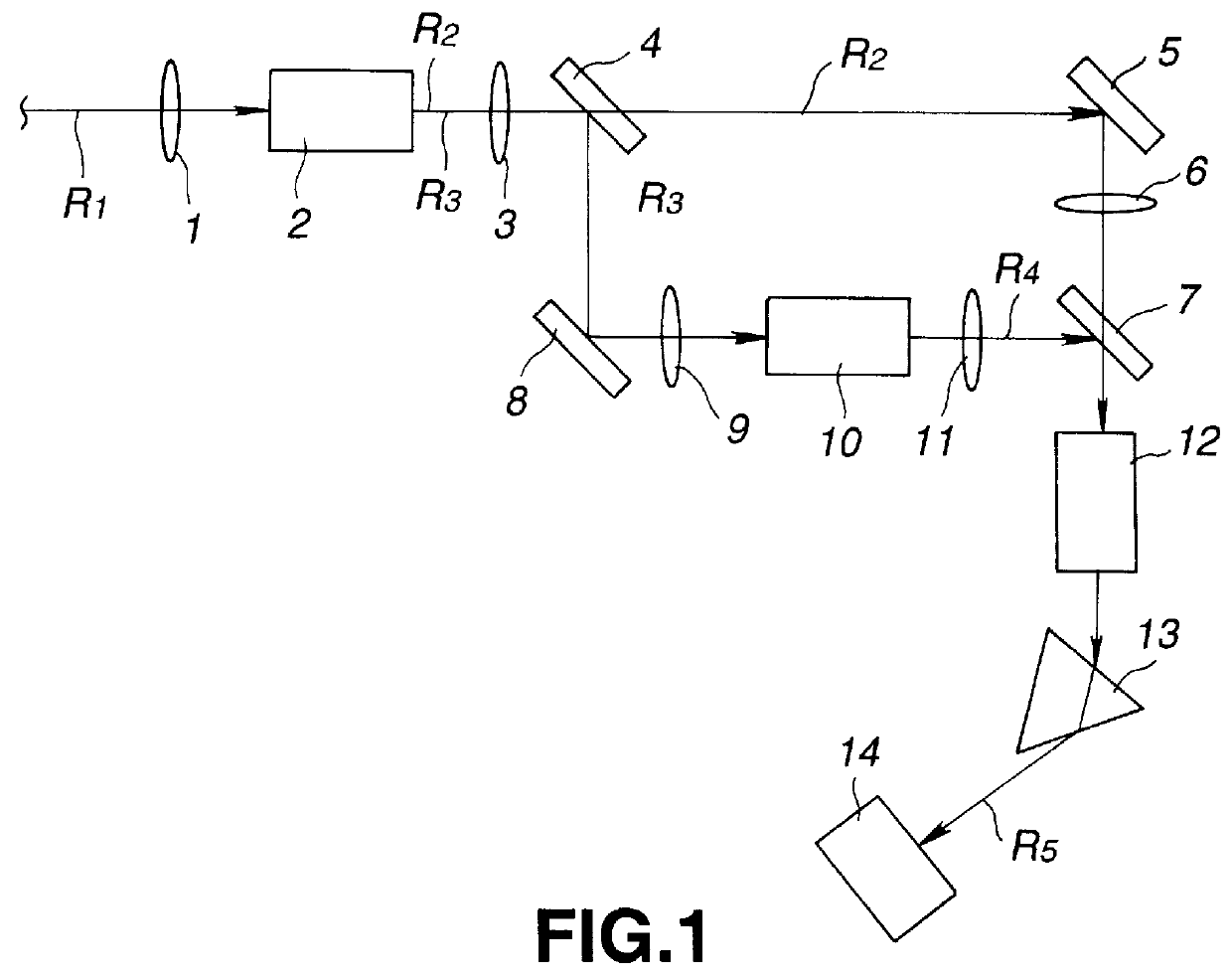
The laser light emission device of the present invention has a light source for generating a continuous wave or pulsed light. From this light source is incident the contiguous wave, which is the continuous wave or the pulsed light, as shown in FIG. 1. This basic wave R.sub.1 is throttled into a non-linear optical crystal 2 for second harmonics generation (SHG) by a lens 1. If the peak power of the basic wave R.sub.1 is high, the basic wave is throttled such that its peak intensity is not in excess of the damage limit of the non-linear optical crystal 2 for second harmonics generation (SHG). As the case may be, the desired efficiency can be achieved without throttling. This non-linear optical crystal 2 for second harmonics generation emits second high harmonics R.sub.3 and the basic wave R.sub.2 transmitted through this optical crystal 2 without conversion.

The second high harmonics R...


PUM

PropertyMeasurementUnit
repetition frequencyaaaaaaaaaa
angleaaaaaaaaaa
wavelengthaaaaaaaaaa

Abstract

A laser light emitting device includes a light source for emitting a continuous-wave laser light beam as a basic wave, a non-linear optical crystal for generating second harmonics, on which the basic wave is incident, a non-linear optical crystal for generating fourth harmonics, on which the second harmonics generated by the non-linear optical crystal for generating second harmonics is incident and a non-linear optical crystal for generating fifth harmonics, on which the basic wave transmitted through the non-linear optical crystal for generating second harmonics and fourth harmonics generated by the non-linear optical crystal for generating fourth harmonics are incident. The non-linear optical crystal for generating fifth harmonics additively mixes these incident waves for generating fifth harmonics. A time-averaged generated output of the second harmonics in the non-linear optical crystal for generating second harmonics is set to 50% to 70% or to 47% to 57% of a time-averaged output of the input wave incident on the non-linear optical crystal for generating second harmonics.

Description

1. Field of the InventionThis invention relates to a laser light emitting device used for fine working or as a light source for a light exposure device or as an illuminating device.2. Description of Related ArtHeretofore, fifth harmonics of a laser light beam were generated by the laser of a low repetition frequency and high peak power. In case of solid-state lasers, the usual practice is to use a substantially collimated light beam, with the beam diameter being set to a larger value for evading damage to the crystal for wavelength conversion, using pulses of an extremely high laser power and a repetition frequency of the order of 1 to 100 pulses per second. However, this system has scarcely been put to practical use because of serious damages to crystals (see R. Kato, Researches in Laser. Vol.18, pp.3 to 7, W. Wiechmann et al., Post Deadline Papers of CLEO, 1995, CPD 19, and K. Deki et al., Extended Abstracts to Lectures of the Society of Applied Physics, 57th Autumnal Meeting, 7-a...

Claims


Application Information

Patent Timeline
Patent Type & Authority Patents(United States)
IPC IPC(8): G02F1/35G02F1/37H01S3/109H01S3/11H01S3/16
CPCG02F1/353G02F2001/3507G02F1/37G02F1/3534G02F1/3507
Inventor MASUDA, HISASHI
Owner SONY CORP
Why Eureka
Try Eureka