Heat-treating boat for semiconductor wafers

a technology of semiconductor wafers and heat-treatment boats, which is applied in the direction of heat-treatment equipment, lighting and heating equipment, furniture, etc., can solve the problems of difficult uniform heat-treatment of wafers, distortion, and crystal defect called slip in the wafer near the supported portions, and achieves the effect of simple structur

Inactive Publication Date: 2000-05-16
TOKYO ELECTRON LTD
View PDF8 Cites 104 Cited by
  • Summary
  • Abstract
  • Description
  • Claims
  • Application Information

AI Technical Summary

Benefits of technology

It is an object of the present invention to provide a heat-treating ring boat having a simple structure that can prevent ring trays from being fixed and dropped.

Problems solved by technology

From these reasons, when the wafer is heat-treated at a high temperature equal to or higher than 1,050.degree. C., a crystal defect called slip tends to occur in the wafer near the supported portions.
Furthermore, in the ring boat, distortion occurs in the trays 19, and it is difficult to uniformly heat-treat the wafers.
Due to the heat during welding, some distortion may occur in the trays 19 to degrade the flatness, and heat-treating having a high planar uniformity cannot sometimes be performed for the wafers.
Hence, welding of the trays 19 requires high precision to make the operation very difficult.
However, a heat-treating boat made of SiC is very expensive.
Since SiC has a high melting point, a member cannot be adhered to the heat-treating boat by welding, making the manufacture difficult.
In other words, in a ring boat made of SiC, ring trays cannot be fixed to the columns by welding.

Method used


Image

  • Heat-treating boat for semiconductor wafers
  • Heat-treating boat for semiconductor wafers
  • Heat-treating boat for semiconductor wafers

Examples


Embodiment Construction

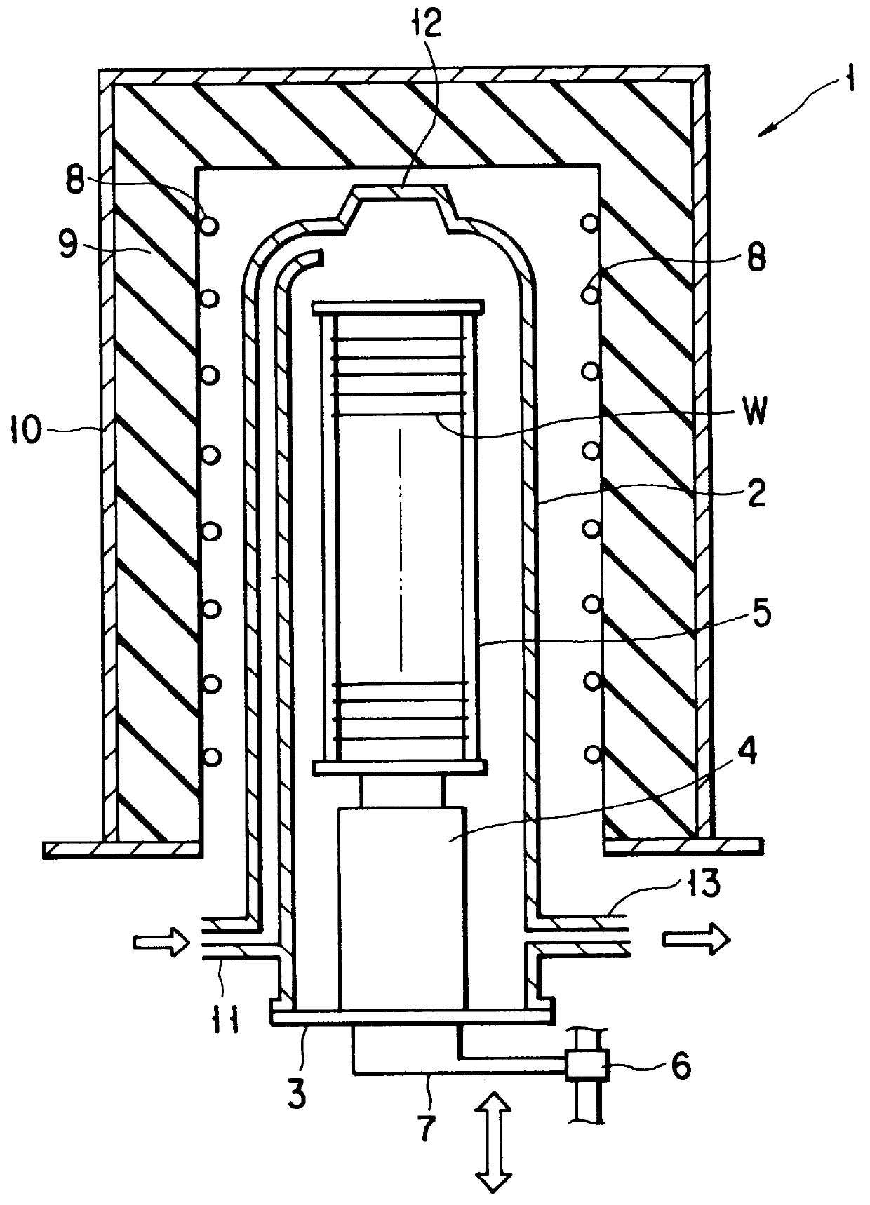
A vertical heat-treating apparatus shown in FIG. 1 is formed to perform oxidation or diffusion for semiconductor wafers at a high temperature of, e.g., about 1,050.degree. C.

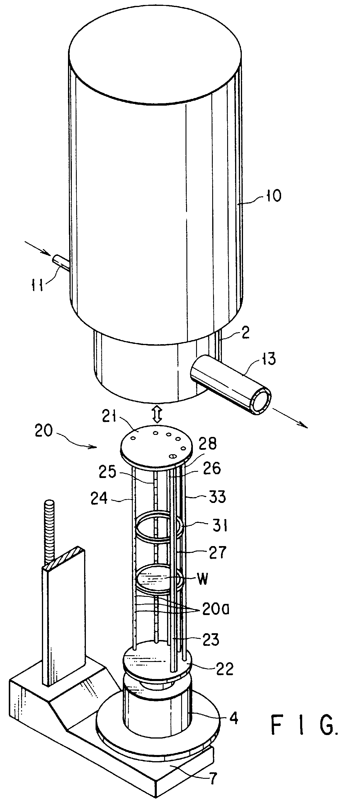
An heat-treating apparatus 1 has a longitudinally cylindrical quartz processing chamber 2 having an open lower end. A lid 3 that opens and closes this lower-end opening portion is arranged under the processing chamber 2 to hermetically seal it. A wafer boat, i.e., a heat-treating boat 5, is placed on the lid 3 through a quartz heat-insulating cylinder 4. A large number of wafers W are horizontally supported in the boat 5 at a predetermined pitch in the vertical direction.

The lid 3 is connected to an elevating mechanism 6 such as a boat elevator through an arm 7 to load / unload the boat 5 in / from the processing chamber 2. Accordingly, when the boat 5 is moved vertically, the lid 3 is opened / closed simultaneously.

A heater 8 is arranged around the processing chamber 2 in a coiled manner to heat the interior of the p...


PUM

PropertyMeasurementUnit
temperatureaaaaaaaaaa
softening pointaaaaaaaaaa

Abstract

PCT No. PCT/JP97/00526 Sec. 371 Date Aug. 31, 1998 Sec. 102(e) Date Aug. 31, 1998 PCT Filed Feb. 25, 1997 PCT Pub. No. WO97/32339 PCT Pub. Date Sep. 4, 1997An heat-treating ring boat (20) for semiconductor wafers (W) has a top plate (21), a bottom plate (22), six columns (23-28), and 63 ring trays (31). The trays (31) are mounted in grooves (20a) of the columns (23-28). To fix the trays (31), a fixing rod (33) is detachably mounted between the top plate (21) and bottom plate (22). A through hole (21a) and a recessed portion (22a) to mount the fixing rod (33) therein are formed in the top plate (21) and bottom plate (22). Notches (34) to engage with the fixing rod (33) are formed in the trays (31). A notch (32) to engage with the fixing rod (33) is formed in the column (23). A projection (41) is formed on each tray (31) to abut against the side surface of the column (24).

Description

The present invention relates to a heat-treating boat for holding a plurality of semiconductor wafers in the processing chamber of a vertical heat-treating apparatus.A vertical heat-treating apparatus is used to perform a heat-treating, e.g., thermal oxidation or thermal diffusion, for a plurality of semiconductor wafers (to be referred to as "wafers" hereinafter) all together, or to perform a so-called batch processing. In the heat-treating apparatus of this type, a large number of wafers are loaded in the processing chamber along with a heat-treating boat that holds the wafers in a stacked state with gaps therebetween, and predetermined heat-treating is performed.FIGS. 35 and 36 are perspective views showing a conventional typical heat-treating boat in the vertical heat-treating apparatus.FIG. 35 shows a heat-treating boat called a ladder boat. This boat has circular top and bottom plates 16 and 17 that are arranged above a heat-insulating cylinder 4 to vertically oppose each othe...

Claims


Application Information

Patent Timeline
Patent Type & Authority Patents(United States)
IPC IPC(8): H01L21/673H01L21/67
CPCH01L21/6875H01L21/67309H01L21/67115H01L21/67098
Inventor SHIMAZU, TOMOHISANAKAO, KEN
Owner TOKYO ELECTRON LTD
Why Eureka
Try Eureka