Process of and a device for producing a gas, containing at least one component, from a gas mixture

a technology of gas mixture and process, which is applied in the direction of chemistry apparatus and processes, separation processes, dispersed particle separation, etc., can solve the problems of affecting the desorption efficiency negatively, the constant adsorption bed, and the inability to achieve the optimum performance of the process

Inactive Publication Date: 2000-05-30
AGA AB
View PDF30 Cites 30 Cited by
  • Summary
  • Abstract
  • Description
  • Claims
  • Application Information

AI Technical Summary

Problems solved by technology

However, in practice the temperature in the adsorption bed is not constant but varies both during the various steps of the cycle and from one point to another within the adsorption bed.
Typically, the molecular sieve particles are heated during the adsorption phase, which influences the adsorption efficiency negatively, and cooled down during the desorption (regeneration), which influences the desorption efficiency negatively.
The temperature gradient may lead to a non optimum performance of the process.
The height of the vessel is merely limited by the handling aspects.
Thus, such a vessel may have a considerable size.

Method used


Image

  • Process of and a device for producing a gas, containing at least one component, from a gas mixture
  • Process of and a device for producing a gas, containing at least one component, from a gas mixture
  • Process of and a device for producing a gas, containing at least one component, from a gas mixture

Examples


first embodiment

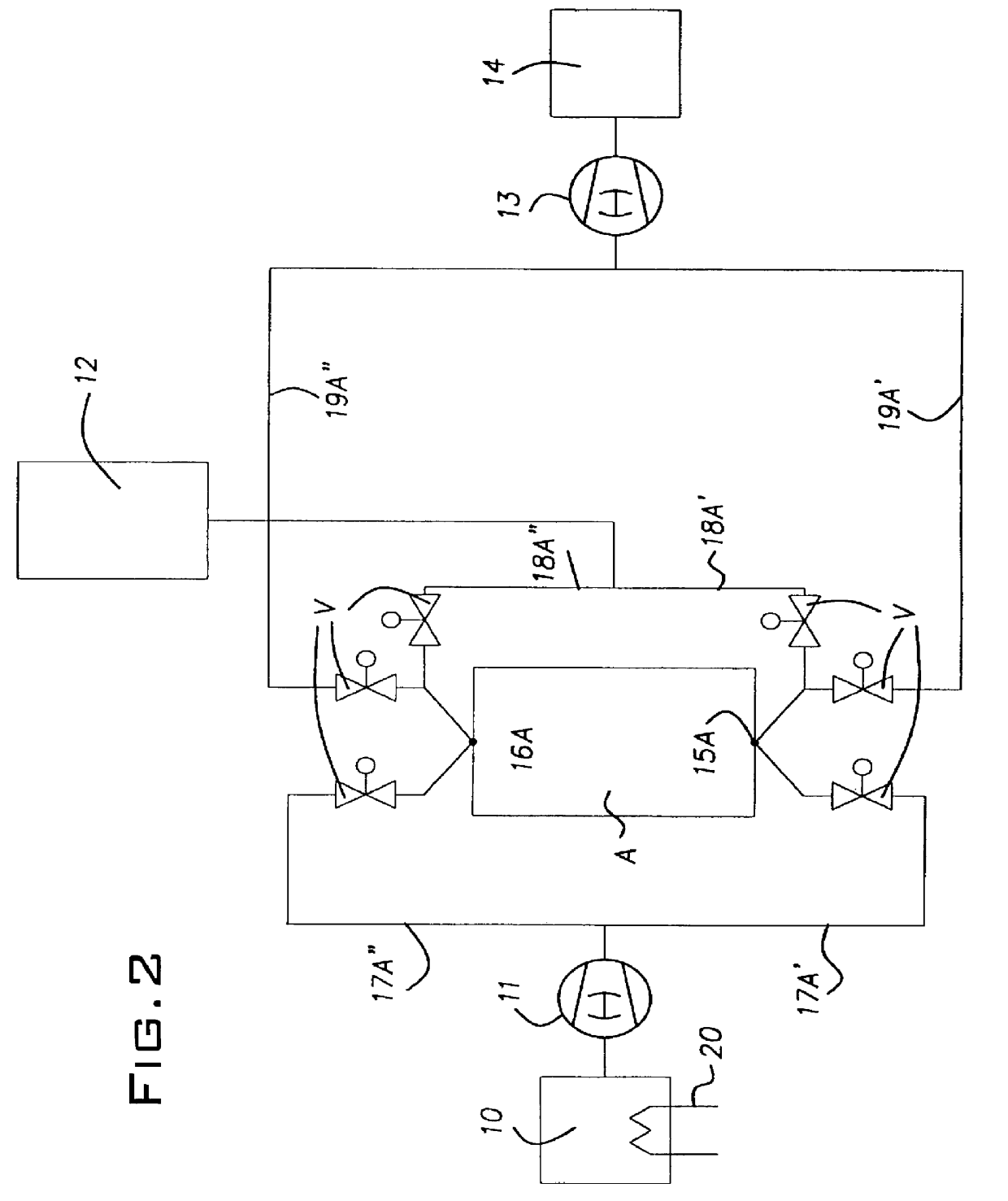
FIG. 2 discloses a separation device according to the present invention. The device, being a pressure swing adsorption apparatus, comprises a source means 10, a pump 11, a vessel A, a product gas receiving means 12, a vacuum pump 13, and a second, rest gas receiving means 14. The source means 10 may be in the form of a container or an inlet device, e.g. in the case of separation of air. The product gas receiving means 12 may be in the form of a container or a pipe means leading directly to a process using the gas produced by the separation device. The second, rest gas receiving means 14 may be in the form of a container or an outlet device leading to the ambient atmosphere. The vessel A is provided with a bed of adsorbing material, such as molecular sieves particles, e.g. in the form of zeolite, a first inlet / outlet passage 15A and a second inlet / outlet passage 16A. This means that gas may be fed through the vessel A in two directions, i.e. a first direction via the first passage 15...
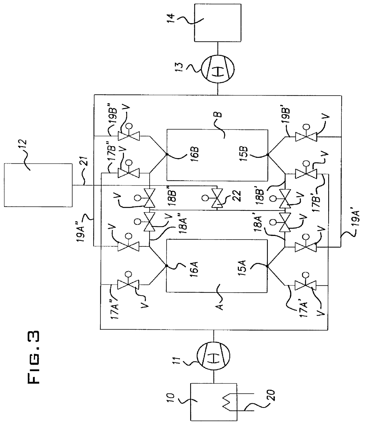
second embodiment

The function of the second embodiment will now be explained with reference to the production. by way of example only, of oxygen by separation of air, cf. also TABLE 2 below.

During the first step of operation, comprising adsorption by the vessel A, as described above in connection with the first embodiment, the vessel B is regenerated by evacuation of the rest gas through the first passage 15B. During an intermediate phase of the first step of operation the valve means V of the conduits 18A" and 18B" are open as well as the valve 22 of the conduit 21, thereby permitting both oxygen purge from the vessel A to the vessel B via the second passages 16A and 16B as well as oxygen supply from the vessel A to the product gas receiving means 12. During an end phase of the first step of operation, the valve 22 of the conduit 21 is then closed, thereby permitting pressure equalisation between the vessels A and B via the second passages 16A and 16B and the conduits 18A" and 18B". During this end...


PUM

PropertyMeasurementUnit
sizeaaaaaaaaaa
temperatureaaaaaaaaaa
pressureaaaaaaaaaa

Abstract

PCT No. PCT/SE97/00332 Sec. 371 Date Dec. 10, 1998 Sec. 102(e) Date Dec. 10, 1998 PCT Filed Feb. 26, 1997 PCT Pub. No. WO97/32658 PCT Pub. Date Sep. 12, 1997A process and apparatus for separating a gas from a gas mixture. The apparatus includes a vessel having an interior with a bed of adsorbent disposed therein. First and second passages communicate with the interior of the vessel. In a first step, the gas mixture is fed to the bed via the first passage and discharged from the bed via the second passage. In a second step, rest gas is evacuated from the bed via the first passage. In a third step, the gas mixture is fed to the bed via the second passage and discharged from the bed via the first passage. In a fourth step, rest gas is evacuated from the bed via the second passage.

Description

TECHNICAL FIELD OF THE INVENTION AND PRIOR ARTThe present invention relates to a process of separating a gas, containing at least one component, from a gas mixture. Moreover, the present invention relates to a device for separating a gas, containing at least one component, from a gas mixture.It is known to produce gases, such as oxygen and nitrogen, by the separation of air. Furthermore, it is known to provide such a separation by means of a so called PSA-process (Pressure Swing Adsorption). A conventional PSA-process uses one or more adsorption beds containing an adsorbent provided in one or more layers. Typically, the adsorbent comprises molecular sieve particles having a size of 1-3 mm. Thus, such a PSA-process may produce oxygen by pressurising air through the adsorbing bed where nitrogen can be selectively adsorbed and being removed from the adsorbing bed by de-pressurization. There are several different processes based on this principle described in patents and literature. All...

Claims


Application Information

Patent Timeline
Patent Type & Authority Patents(United States)
IPC IPC(8): B01D53/047
CPCB01D53/0476B01D53/0423B01D2259/402B01D53/053B01D2253/108B01D2253/304B01D2256/10B01D2256/12B01D2256/18B01D2256/22B01D2257/102B01D2257/80B01D2259/40022B01D2259/4003B01D2259/40035B01D2259/40045B01D2259/40052B01D2259/40062B01D2259/40079B01D2259/40081B01D2259/401
Inventor ZHENG, GUHONG
Owner AGA AB
Why Eureka
Try Eureka