Weight-filling method, and a corresponding device

a technology of receptacle and weight, applied in the direction of weighing apparatus, liquid bottling, packaging goods, etc., can solve the problems of reducing productivity and high installation cost, and achieve the effect of avoiding variations in the point of application of weight and ensuring accuracy of weight measurements

Inactive Publication Date: 2000-06-13
SERAC GROUP
View PDF7 Cites 95 Cited by
  • Summary
  • Abstract
  • Description
  • Claims
  • Application Information

AI Technical Summary

Benefits of technology

This causes the collar to have point support on the top surfaces of the jaws of the clamp. When the weighing device is mounted on a rotary platform, this disposition makes it possible to avoid variations in the point of applica

Problems solved by technology

The installation then requires means for adjusting the position of the weighing device, thereby making the installation expensive,

Method used


Image

  • Weight-filling method, and a corresponding device
  • Weight-filling method, and a corresponding device
  • Weight-filling method, and a corresponding device

Examples


first embodiment

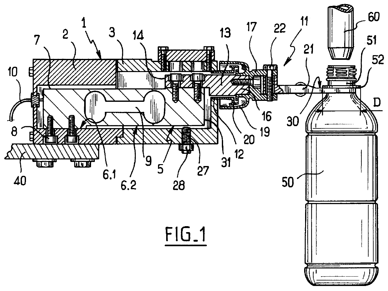
With reference to FIGS. 1 and 2, the receptacle weighing device in the first embodiment comprises a structure given overall reference 1 constituted by an edge of the platform 40 to which there is fixed a box comprising two hollow portions 2 and 3 that are connected to each other.

A bar 5 of elastically deformable material is fixed to the structure 1, via a portion 6.1 of the bottom surface of the bar that is adjacent to an end 7 of the bar 5, while the remainder 6.2 of the bottom surface is projecting.

In known manner, the bar 5 has a strain gauge (not shown) designed to be connected to a filling control unit via an electrical conductor 10, and also an elongate through slot 9 to form a weight sensor of constant moment.

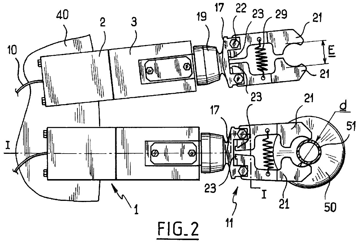
A support member given overall reference 11 extends laterally relative to the structure 1 through an opening 12 formed in box portion 3. The support member 11 has an arm 13 with an end 14 fixed on the top face of the bar 5 by screws and an opposite end 16 carrying a fork...

second embodiment

Elements that are identical or analogous to those described above are given the same numerical references in the following description of the

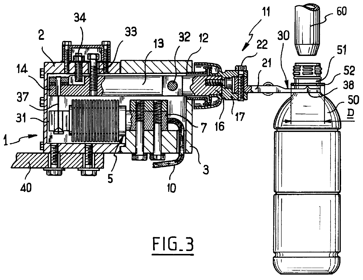
With reference to FIGS. 3 and 4, in the second embodiment, the box-forming portion 3 of the structure 1 has a bottom inside surface that is raised relative to the bottom inside surface of the portion 2. The elastic bar 5 is mounted the opposite way round to the previous embodiment, i.e. the end 7 of the bar 5 is fixed to the bottom inside surface of the portion 3 by screws.

The free end 31 of the bar 5 is connected via a link 37 to the end 14 of an arm 13 that is mounted to pivot in the portion 3 about a pivot axis 32. The end portion 16 of the arm 13 carries a fork 17 and jaws 21 pivotally mounted on the fork 17 in a manner analogous to that of the first embodiment.

The top faces of the jaws 21 are provided with projecting portions 38 constituted by ridges extending along a diameter of the opening defined by the jaws 21 perpendicularly to the lo...


PUM

PropertyMeasurementUnit
Diameteraaaaaaaaaa

Abstract

A method of weight-filling a receptacle having a cylindrical neck and a collar extending around the neck, comprising the steps of suspending the receptacle by the collar and filling and weighing the receptacle while it is suspended, and a weight-filler device for filling, by means of a filler spout, a receptacle having a cylindrical neck and a collar extending around the neck. The device has a weighing device including a holding element having a top surface forming a support for the collar of the receptacle so that the receptacle extends vertically beneath the filler spout and is cantilevered out from a support member mounted on a structure to extend laterally therefrom and associated with a weighing sensor comprising an elastically flexible bar having one end rigidly secured to the structure and an opposite end connected to the support member so that the support member extends substantially horizontally irrespective of a presence of an absence of a container on the support member.

Description

The present invention relates to a method of weight-filling a receptacle having a neck and a collar extending around the neck, e.g. a receptacle such as a bottle, and the invention also relates to a corresponding weight-filling device.Known installations for weight-filling a receptacle having a neck generally comprise a weighing device which includes a weight sensor surmounted by a tray for supporting a receptacle. The weighing device is disposed so that its tray supports the bottom of the receptacle while the neck of the receptacle is positioned immediately beneath a filler spout. When the installation is designed to fill series of receptacles of different heights, then the position of the tray of the weighing device needs to be adjusted every time the series is changed so as to be adapted to the height of the receptacles in the new series. The installation then requires means for adjusting the position of the weighing device, thereby making the installation expensive, or else the ...

Claims


Application Information

Patent Timeline
IPC IPC(8): B67C3/20B67C3/24B67C3/02G01G3/00G01G19/00G01G3/14G01G19/18B65B3/26G01G13/24B65B3/28G01G13/00G01G13/04G01G13/28
CPCB67C3/202G01G19/18G01G3/1402B67C3/242G01G23/005
Inventor GRAFFIN, ANDRE
Owner SERAC GROUP
Why Eureka
Try Eureka