Storm drain liner

a filter system and stormwater technology, applied in the direction of sewage draining, separation processes, ways, etc., can solve the problems of heavy metals and hydrocarbons leaching, high contamination, sediment contained in stormwater run-off also creating problems, etc., and achieve the effect of increasing the flow rate through the filter

Inactive Publication Date: 2000-07-11
PACTEC
View PDF42 Cites 152 Cited by
  • Summary
  • Abstract
  • Description
  • Claims
  • Application Information

AI Technical Summary

Benefits of technology

It is a further object to provide a filter that is not susceptible to breaking, while at the same time providing an increased flow rate through the filter.

Problems solved by technology

A problem associated with stormwater run-off is contamination with heavy metals and hydrocarbons which have leaked onto the streets and highways from a variety of sources.
Sediment contained in the stormwater run-off also creates problems.
Many times the contamination is so high that the storm water discharge exceeds the pollution limits imposed by federal and state laws.
The problems associated with this device are that the bag is susceptible to breaking for lack of support from below and that the flaps can become dislodged from between the basin recess and drain grating thereby causing the system to become inoperable.
A further problem associated with the Logue device is the use of a woven polypropylene material.
The woven material and lack of overflow outlets restrict the maximum flow rate through the system to about 40 gallons per minute per square foot and causes water flow to back up during heavy downpours, resulting in flooding around the drain.
The use of a woven material also prevents the material from effectively filtering out the heavy metals and hydrocarbons.
As noted therein, the prior art filter systems using bags are constructed from material that is susceptible to breaking because of its short lifespan.
Furthermore, the systems have no capability to allow storm water out of the system during period of heavy flow, causing flooding in surrounding areas.
However, because these flaps open outwards, they can allow unfiltered water out of the system even when the filter is not full.
However, this can become expensive and time consuming.

Method used


Image

  • Storm drain liner
  • Storm drain liner
  • Storm drain liner

Examples


Embodiment Construction

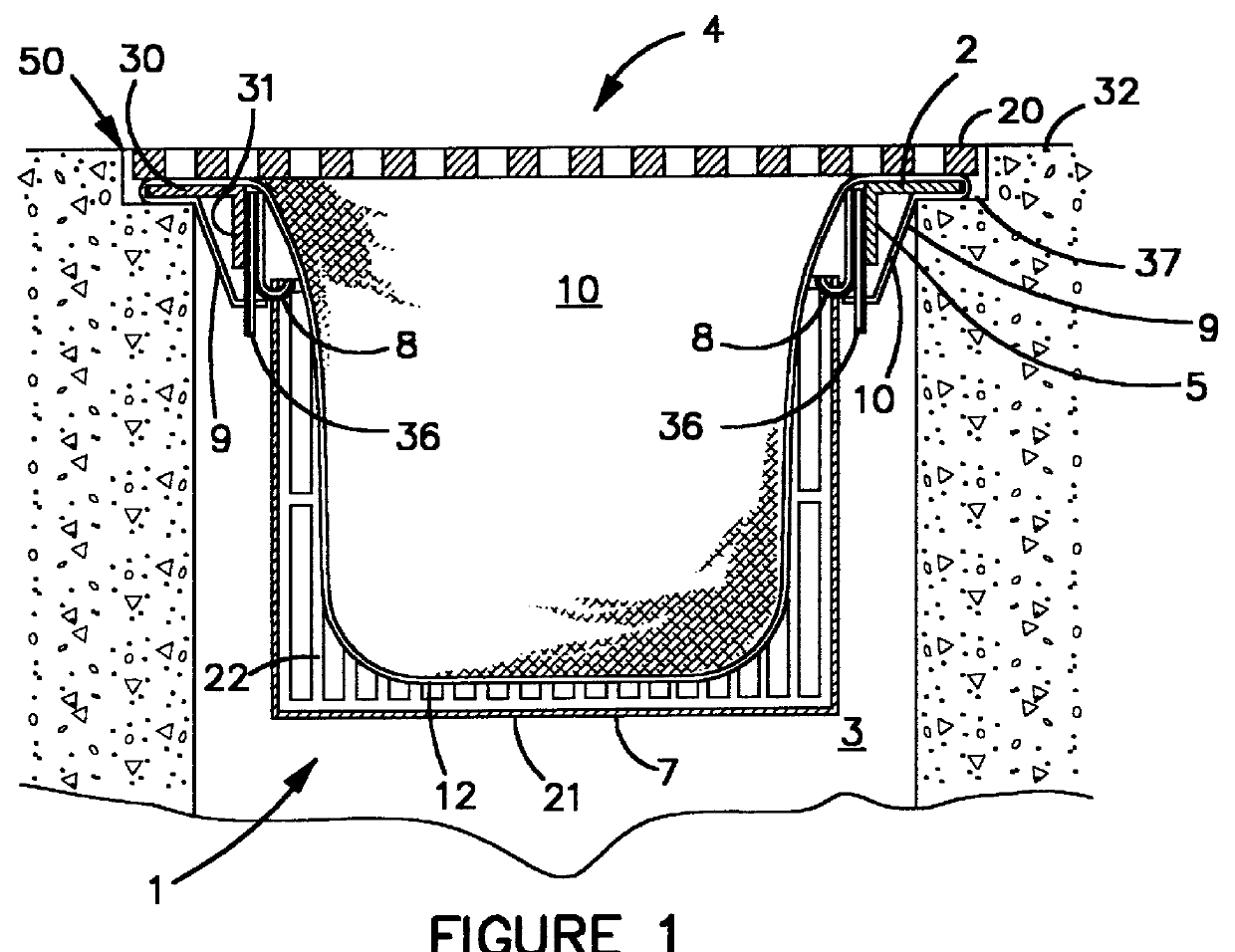
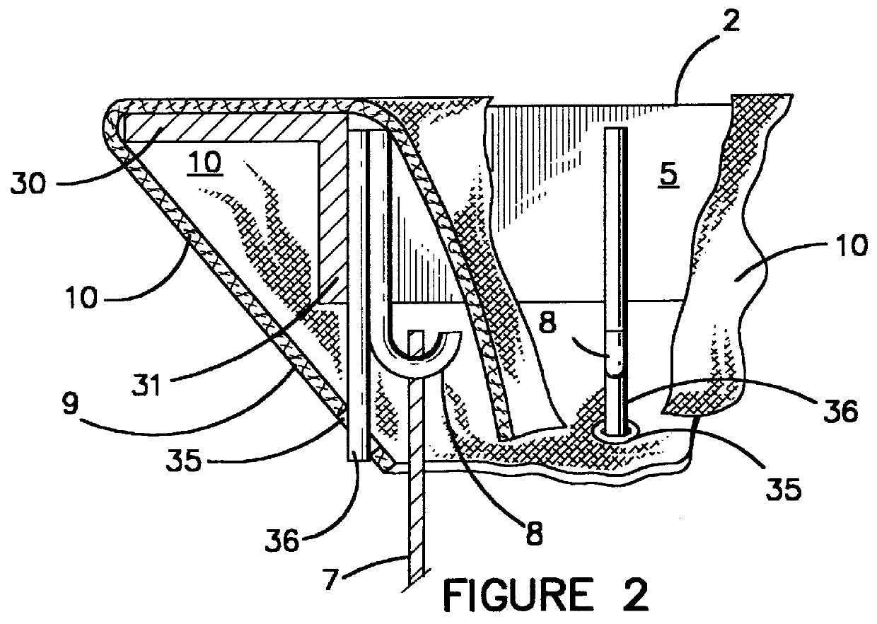
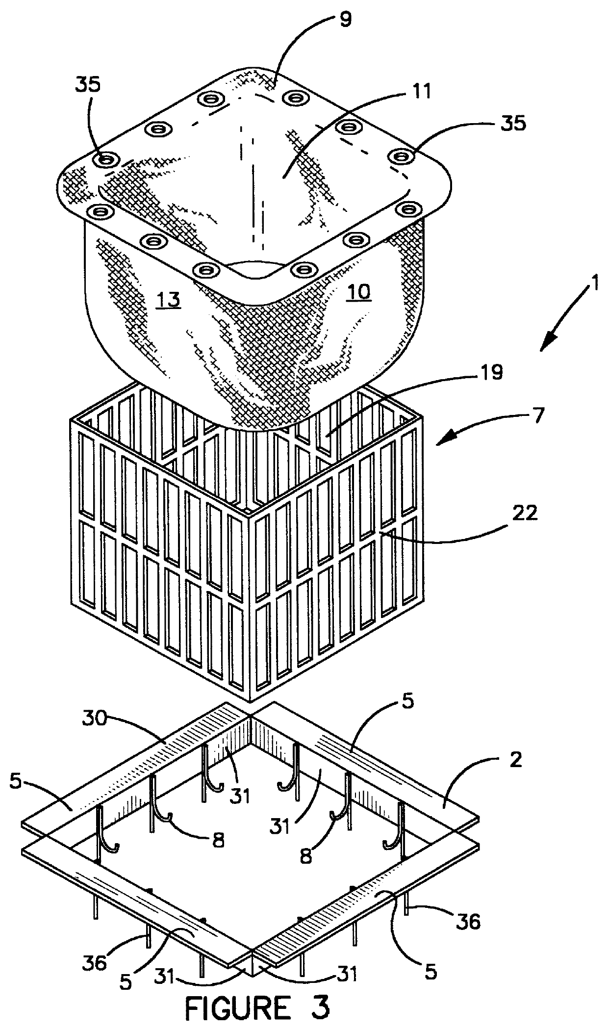
As shown in FIGS. 1-3, drain filter system 1 comprises, generally, a basket 7 having an open top 19 with a grated bottom 21 and grated side walls 22. Basket 7 is positionable within drain 4 between inlet 50 and an outlet (not shown). As used herein, inlet 50 is the area where liquid first flows into drain 4 from ground level 32. A filter 10 is positionable is least partially within basket 7 so that substantially all water passing through inlet 50 flows through filter 10. Drain filter system 1 may rest on the bottom of the drain (not shown) but is preferably positioned above the drain bottom and the outlet as described herein and shown in the Figures.

Drain filter system 1 comprises a frame 2 positionable within drain 4. Most drains 4 have a recess 37 below ground level 32 where a drain grate 20 rests. Drain grate 20 prevents large objects from falling into drain 4. Frame 2 has sides 5, which are expandable (see FIG. 4) so that system 1 can be easily positioned in nearly all existing ...


PUM

PropertyMeasurementUnit
lengthsaaaaaaaaaa
corrosion resistantaaaaaaaaaa
sizeaaaaaaaaaa

Abstract

A drain filtering system is disclosed, comprising a filter placed within a basket which is suspended from frame positioned underneath a drain grate atop the inlet to a storm drain. The filter is constructed from materials which filter out heavy metals and hydrocarbons from the water passing through. The filter also has overflow outlets to prevent back-up of storm water during periods of heavy rain. The basket is constructed from a corrosion resistant material, preferably high density polyethylene which can withstand the extreme pressures exerted by waste and water collected within the filter.

Description

1. Field of the InventionThis invention relates to filtering systems, more particularly filtering systems used in storm drains.2. Prior ArtStormwater flows into storm drains, often located on or near a street or highway, and into under ground lines. A problem associated with stormwater run-off is contamination with heavy metals and hydrocarbons which have leaked onto the streets and highways from a variety of sources. Sediment contained in the stormwater run-off also creates problems. Many times the contamination is so high that the storm water discharge exceeds the pollution limits imposed by federal and state laws. Thus, a need exists for a water-filtering device that can filter out heavy metal and hydrocarbon contaminants.Prior attempts have been made to design filtering systems placed below the surface of the drain within the drain basins. For example, U.S. Pat. No. 4,419,232 to Arntyr et al. discloses a two-tier system whereby a coarse material filter is placed above a finer fi...

Claims


Application Information

Patent Timeline
Patent Type & Authority Patents(United States)
IPC IPC(8): B01D39/16B01D29/23B01D29/13B01D29/27E03F1/00
CPCB01D29/23B01D29/27B01D39/1623E03F1/00E03F5/0404B01D29/96
Inventor SCHILLING, MICHAEL R.CORN, DANIEL PAUL
Owner PACTEC
Why Eureka
Try Eureka