Method and apparatus for extinguishing fires

a fire extinguishing and apparatus technology, applied in the field of fire extinguishing, can solve the problems of high toxicity of combustion products of pyrotechnic composition, 12% kclo.sub.4, % kno, % c.sub.3 h.sub.5 o, etc., and achieve the effect of large coolant flow velocity, low efficiency of combustion products cooling, and high toxicity

Inactive Publication Date: 2000-07-18
R AMTECH INT
View PDF14 Cites 61 Cited by
  • Summary
  • Abstract
  • Description
  • Claims
  • Application Information

AI Technical Summary

Problems solved by technology

A serious disadvantage of this method and apparatus lies in the fact that the combustion products of the pyrotechnic composition, which consists of 12% KClO.sub.4, 60% KNO.sub.3, 18% C.sub.3 H.sub.5 O, and 10% Mg, are highly toxic.
The use of carbonates, hydrates, and oxalates as cooling media results in an additional increase in the concentration of toxic gases that are released when the cooling medium reacts with the hot gas and aerosol mixture.
The water vapor that is released can react with chlorine, nitrogen oxides, and carbon dioxide to form acids--HCl, HNO.sub.3, H.sub.2 CO.sub.3 --which are also harmful for living organisms and for other objects present in the fire area.
This also results in an increased quantity of the toxic gases that are formed upon decomposition of the cooling medium.
The composition has a broad combustion temperature profile (from the condensing phase of the composition to the hottest point of the flame), whereby it is difficult to cool the gas and aerosol mixture.
More specifically, although there is a low content of such gases as CO.sub.2 and NH.sub.3 in the combustion products, the problem of toxicity is not fully resolved, because the concentrations of products of incomplete oxidation such as CO, NO, HNC are rather high.
Low efficiency of the process of complete oxidation of the products of incomplete combustion.
The concentration of oxygen that is taken from the air in a jet flow is not sufficient to ensure the complete oxidation of the gases that are formed when the composition burns.
This would cause an increase in the pressure within the combustion chamber, which would require a greater strength of the casing.
In case an oxidizer is to be supplied from a special pressurized gas bottle, which is required in some applications, the construction of the apparatus becomes more expensive.
Low efficiency of cooling of the combustion products with a liquid coolant by means of a known cooling system.
In order to meet these requirements, a much larger metal container would be necessary, thus complicating the practical application of the device.
The main disadvantage of this method is inefficient application of the oxidation catalysts.
This results in the process of complete oxidation of the combustion products having a low efficiency, which, in turn, causes a higher level of toxic gases in the gas and aerosol mixture.
The above-mentioned catalysts in the gas and aerosol mixture generating composition or on the surface thereof have a catalytic effect on the reactions of decomposition of components that are present in the condensed phase of the composition but they do not have any practical effect on the reactions in the gas phase.
As a result, the composition will burn either too slowly or too rapidly.
This would not permit complete oxidation of the combustion products.
As a consequence of this, the gas temperature during the gas passage through the heat-absorbing charge decreases, thus lowering the efficiency of the complete oxidation.
The efficiency of a special oxidizer filling that is located directly in front of the discharge port is also not very high.
Since the velocity of flow through the oxidizer filling is high, the reaction of total oxidation is not completed.
This will result in lower discharge velocity and also in higher pressure build-up in the casing of the apparatus, which may cause the casing to blow up.
Therefore, the state of the art does not allow the required properties to be obtained simultaneously, namely:
The above-described fire-extinguishing method cannot be used to its full advantage with the employment of prior art devices.
This prior art apparatus is disadvantageous primarily because it cannot ensure generation of a non-toxic gas and aerosol mixture.
This is due to the fact that the cooling section is positioned in front of the discharge port, and the cooling process itself results in toxic carbon monoxide being released, which is admitted with the gas and aerosol mixture to the space being protected without complete oxidation and filtration.
The above-described apparatus is deficient primarily due to the high toxicity of the fire-extinguishing gas and aerosol mixture.
This disadvantage stems from the choice of oxidizer.

Method used


Image

  • Method and apparatus for extinguishing fires
  • Method and apparatus for extinguishing fires
  • Method and apparatus for extinguishing fires

Examples


first embodiment

The second embodiment of the apparatus shown in FIGS. 5 through 7 differs from the first embodiment by the fact that it has two cooling sections 9a, 9b that are spaced apart by interposition of a spacer ring 11d. The complete oxidation section 6 has four flow-through passages 15 extending lengthwise of the casing 1 and in which four flow-through passages 17 extend lengthwise of the casing 1 adjacent to the section 9a and adjacent to the passages 15. The spring 10 is provided under the composition 4 in the casing 1 to prevent the composition 4 from adhering to the walls of the heat insulating layer 12. The igniter 5 is installed in a central passage of the composition 4.

third embodiment

In the apparatus shown in FIGS. 8 and 9, there are two cooling sections 9a, 9b, and the spring 10 is positioned between the gratings 8d, 8e defining these sections. There are no passages in the sections 6 and 9a, 9b. The periphery 16 of the casing 1 has fins for heat insulation. A heat insulating material, e.g., such as zeolite particles, fills the space between the fins. The igniter 5 is offset from the central position in the composition.

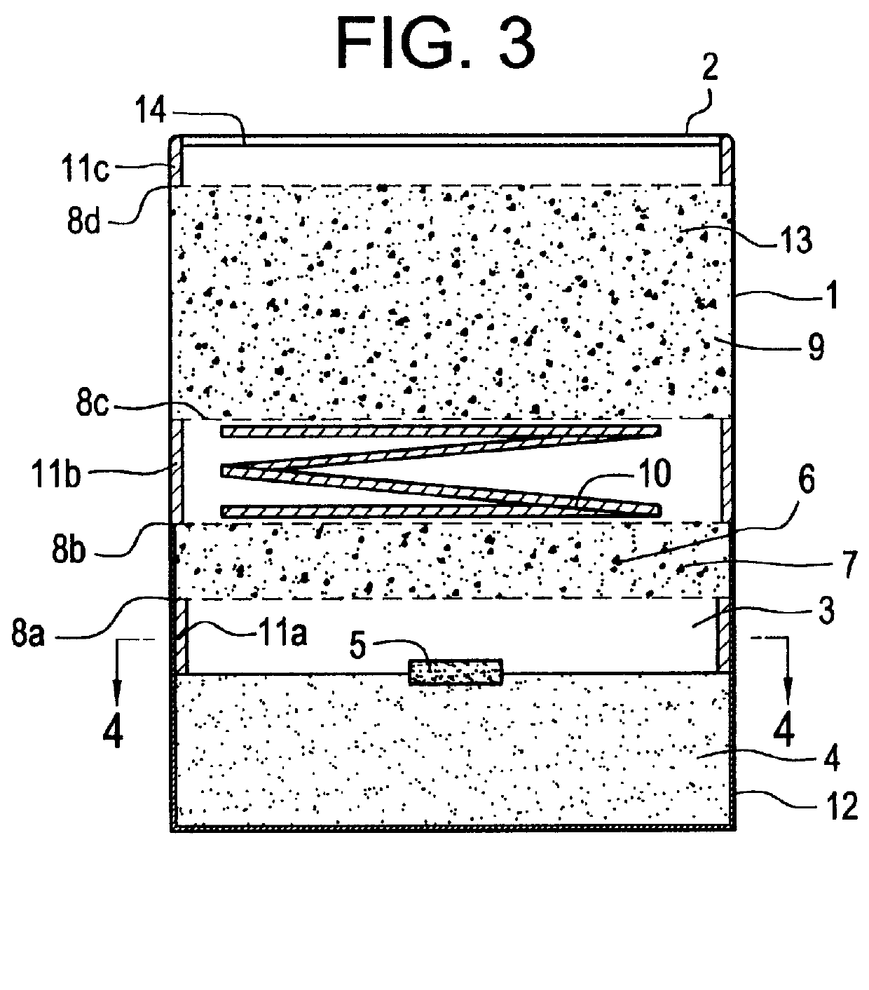
The apparatus shown in FIG. 3 functions in the following manner.

In the case of fire, the igniter 5 of the pyrotechnic composition 4 provided in the combustion chamber 3 is initiated. The burning pyrotechnic composition 4 releases a hot gas and aerosol mixture that consists of a solid phase of the aerosol particles (K.sub.2 CO.sub.3, KHCO.sub.3, NH.sub.4 HCO.sub.3, KNO.sub.2, C, etc.) and a gas phase (CO, CO.sub.2, NO, NO.sub.2, HCN, NH.sub.3, CH.sub.4, H.sub.2 O). The resulting gas and aerosol mixture passes through the meshes of the grating 8a in...


PUM


Abstract

A method for extinguishing fire, wherein a gas an aerosol mixture is fed into a space includes steps of igniting a pyrotechnic composition that ensures a predetermined temperature profile during burning and a predetermined composition of the gas and aerosol mixture completely oxidizing the combustion products of incomplete combustion of the pyrotechnic composition by causing them to pass through a bed of catalytically active substances, which is located in the zone of the maximum temperature of the temperature profile of combustion of the pyrotechnic composition, with the temperature remaining constant by redistribution of said profile; cooling the combustion products and completely oxidizing them by reacting with substances having high heat absorbing capacity, concurrently with the filtering of the combustion products according to composition of the gas phase and particle size of the aerosol phase. An apparatus for extinguishing fire, having a casing (1) that has a discharge port (2), a combustion chamber (3) that is accommodated in the casing (1) and heat insulated from the walls of the casing (1), a pyrotechnic composition (4) and an igniter (5) that are received in the combustion chamber, a cooling section (9) and a complete catalytic oxidation section (6) that has a pair of spaced metal gratings (8a, 8b) between which a catalytically active substance is placed and that is located at a fixed distance from the pyrotechnic composition (4). A compensation device (10) is provided for maintaining the above-mentioned fixed distance during the burning of the pyrotechnic composition (4).

Description

The invention relates to fire fighting, and, more specifically, deals with a method for fire extinguishing with gas and aerosol mixtures that are released in burning pyrotechnic compositions.DESCRIPTION OF THE BACKGROUND ARTRussian Patent 2 072 135 presents a method for fire extinguishing wherein a gas and aerosol mixture is released when a pyrotechnic charge burns, the mixture reacting with the combustion products in the fire area and resulting in the fire being extinguished. Before being supplied to a protected area, the gas and aerosol mixture is cooled; for that purpose, the mixture is combined with substances that have a high heat-absorbing capacity and a high degree of degassing such as carbonates, hydrates, hydroxides, and oxalates, which are used in the form of pellets or tablets.An apparatus for carrying out this method has a casing that contains a pyrotechnic composition, a heat protection layer, and a discharge port. A pyrotechnic composition is ignited by means of a stan...

Claims


Application Information

Patent Timeline
Patent Type & Authority Patents(United States)
IPC IPC(8): A61D1/06A61D1/00A62C39/00A62C5/00A62C99/00
CPCA61D1/06A62C5/006A62C99/0018
Inventor DRAKIN, NIKOLAY VASILYEVICH
Owner R AMTECH INT
Why Eureka
Try Eureka