Bandwidth broadened and power enhanced low coherence fiberoptic light source

Inactive Publication Date: 2000-07-18
JDS UNIPHASE INC
View PDF3 Cites 31 Cited by
  • Summary
  • Abstract
  • Description
  • Claims
  • Application Information

AI Technical Summary

Problems solved by technology

The power level of the source is also of concern, since the sensor system loss budget can be greater with a higher power optical source.
In the case of fiber optic temperature or strain sensing,

Method used


Image

  • Bandwidth broadened and power enhanced low coherence fiberoptic light source
  • Bandwidth broadened and power enhanced low coherence fiberoptic light source
  • Bandwidth broadened and power enhanced low coherence fiberoptic light source

Examples


Embodiment Construction

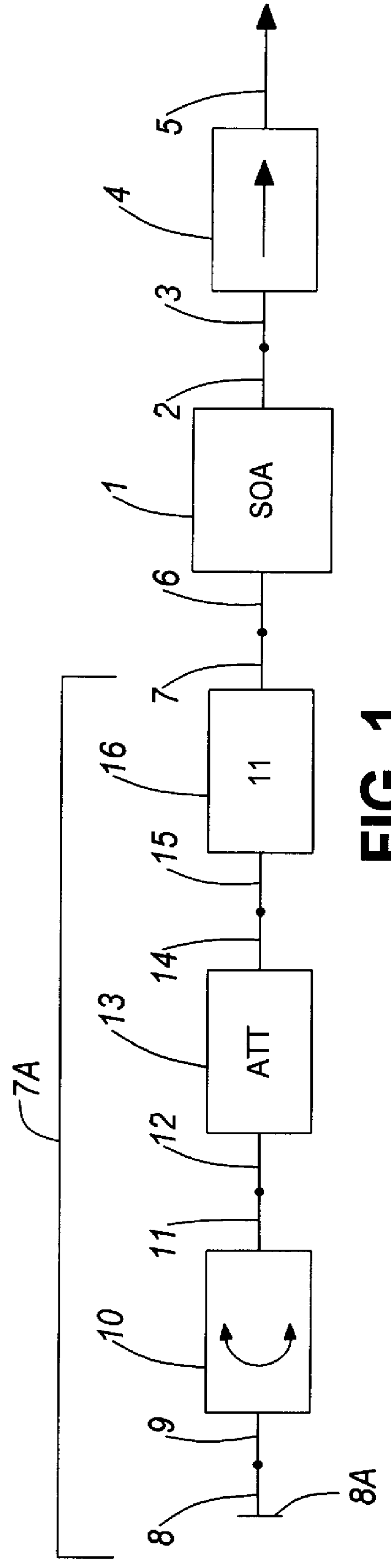
As shown in FIG. 1, a semiconductor optical amplifier 1 is an example of an amplification medium used in this embodiment. The amplifier has two output ports, one being an output port 2 and another being a backward propagating port 6. The output port 2 is fusion spliced to the input 3 of a single or double stage polarization independent optical isolator 4. The output 5 of the isolator is the output of the entire device. The purpose of the isolator 4 is to avoid perturbation of the back reflection after output, and therefore this element can be deleted if other means are taken to avoid this perturbation.

The backward propagating port 6 is fusion spliced to the input 7 of a control loop 7A. In this embodiment, a single arm control loop is shown, although a multi-arm control loop can be used, as will be described later.

The loop 7A is comprised of a reflector 8A formed of a gold-covered tip of an optical fiber carrying the optical signal. The fiber pigtail 8 which ends in the reflector 8A...


PUM


Abstract

An optical light source signal generator comprising an optical amplification medium for generating amplified spontaneous emission (ASE), having forward and backward light propagating ports for outputting output and backward optical light respectively, a reflector for reflecting the backward propagating optical light back toward the backward light propagating port, and an optical light spectrum reshaper interposed between the reflector and the backward light propagating port for transmitting the reflected light to the backward light propagating port with a wavelength dependence having a reduced amplitude in a band coinciding with an undesired high gain band of the optical amplification medium.

Description

This invention relates to the field of optical light sources, and in particular to an optical low coherence light source having broad spectrum width and emitting single transverse mode light of which the intensity is typically a few thousand time stronger than regular light emitting diodes (LEDs).BACKGROUND TO THE INVENTIONLow coherence broadband optical sources are required for optical imaging and optical sensors. Such sources are used for example in coherence domain optical tomography, some medical diagnostic technology such as Doppler velocimeters, remote sensors for detecting temperature, pressure, strain, etc., low coherence light source based fiber optic gyroscopes, fiber optic instrumentation, etc.Such applications have very high optical light source spectrum width and shape requirements as well as power density of the main optical emitter or lighting device. For example, in optical imaging, the imaging resolution, defined by RES=f(.lambda.)*1 / .DELTA..lambda., .DELTA..lambda....

Claims


Application Information

Patent Timeline
IPC IPC(8): H01S5/50H01S5/00H01S5/14H01S5/12
CPCH01S5/146H01S5/50H01S5/1209H01S5/1215H01S2301/02
Inventor YANG, DAN DAN
Owner JDS UNIPHASE INC
Why Eureka
Try Eureka