Scintillator based microscope

a microscope and scintillator technology, applied in the field of scintillator based microscopes, can solve the problems of limited range of contrast or latitude of film, inability to display the entire range of contrast in many objects of interest, and many limitations of film-screen x-ray devices, etc., to achieve high resolution geometric magnification and high resolution image

Inactive Publication Date: 2000-07-18
TREX ENTERPRISES CORP
View PDF22 Cites 31 Cited by
  • Summary
  • Abstract
  • Description
  • Claims
  • Application Information

AI Technical Summary

Problems solved by technology

There are several limitations to film-screen x-ray devices.
A major limitation is that the film serves the combined purpose of both the image acquisition function and the image display function.
In addition, the range of contrast or latitude of the film is too limited to display the entire range of contrast in many objects of interest.
Because of the limited latitude and dual acquisition / display function of film, a film-screen x-ray is often overexposed in one area and underexposed in another area due to the thickness and composition variations of the object across the image.
The gray-scale level of x-ray film has a sigmoidal response as a function of exposure which results in difficulties in distinguishing contrast differences at the extremes of the exposure range; that is, in the most radiodense and in the most radiolucent areas of the image.
Current digital x-ray devices have fairly limited resolution and so they are limited in their applications.

Method used


Image

  • Scintillator based microscope
  • Scintillator based microscope
  • Scintillator based microscope

Examples


first embodiment

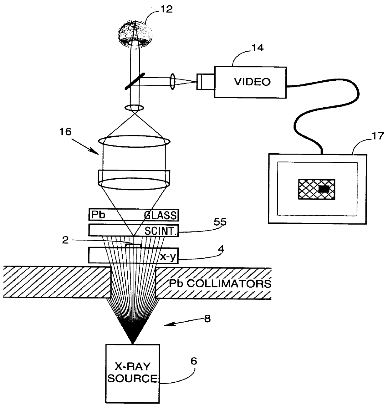
A first embodiment of the present invention can be described by reference to FIG. 1. A target 2 is mounted on an x-ray transparent x-y translation stage 4. An x-ray source 6 is mounted below sample 2 so that its x-ray beam 8 is directed through target 2 to scintillator assembly 55. A portion of the x-ray photons in beam 10 are stopped by target 2 producing a shadow image of target 2 at the illumination surface of scintillation assembly 55. X-ray photons impinging on scintillator assembly 55 produce scintillations in scintillation assembly 55 and light from these scintillations are detected by human eye 12 or video camera 14 through microscopic optical system 16. The image detected by video camera 14 can be displayed on monitor 17. A leaded glass plate assures that human viewers and electronic equipment is not exposed to the x-radiation.

CsI Sandwich

FIGS. 6A through 6D display, in detail, our currently preferred method for fabricating the scintillator assembly 55. It is very important...


PUM


Abstract

A scintillation based microscope. One surface of a single crystal salt crystal scintillator is supported on an optically transparent support plate. The opposite surface, an illumination surface, of the crystal is coated with an optically reflecting material which is transparent to high energy photons (such as x-ray and / or high energy ultraviolet photons) in order to provide a scintillation sandwich having an optical mirror at the illumination surface of the crystal. These high energy photons are directed through a target to create a shadow image of the target on the illumination surface of the scintillator salt crystal. A portion or all of the shadow image is viewed with an optical device such as an eye piece to provide a very high resolution image of the target or portions of the target. In a preferred embodiment an adjustable pin hole unit is described to produce a very small x-ray spot source for producing high resolution geometric magnification of the shadow image of the target.

Description

BACKGROUND OF THE INVENTIONIn most microscopes, the visible light spectrum is used for imaging. X-ray microscopes are known. Two principal advantages of an x-ray microscope over a visible light microscope are (1) better potential resolution of extremely small features due to shorter wavelengths; and (2) some internal features can be observed which cannot be seen with a visible light microscope.Most x-ray imaging devices involve directing a beam of x-rays through an object onto a phosphor screen which converts each x-ray photon into a large number of visible photons. The visible photons expose a sheet of photographic film placed close to the phosphor thus forming an image of the attenuation of x-rays passing through the object.There are several limitations to film-screen x-ray devices. A major limitation is that the film serves the combined purpose of both the image acquisition function and the image display function. In addition, the range of contrast or latitude of the film is too ...

Claims


Application Information

Patent Timeline
Patent Type & Authority Patents(United States)
IPC IPC(8): G21K7/00
CPCG21K7/00G21K4/00
Inventor TRISSEL, RICHARDHORTON, STEVESPIVEY, BRETTMORSELL, LEE
Owner TREX ENTERPRISES CORP
Why Eureka
Try Eureka