Apparatus and method for reducing imaging errors in imaging systems having an extended depth of field

an imaging system and depth of field technology, applied in the field of apparatus and methods for reducing imaging errors in imaging systems having an extended depth of field, can solve the problems of reducing the optical efficiency of the system, introducing distortions in the imaging system, and reducing the numerical apertur

Inactive Publication Date: 2000-08-01
HAND HELD PRODS
View PDF15 Cites 256 Cited by
  • Summary
  • Abstract
  • Description
  • Claims
  • Application Information

AI Technical Summary

Problems solved by technology

The errors and distortions introduced by the imaging system include, among others, lens aberrations, such as spherical and chromatic aberrations, misfocus errors resulting from an object being located away from the position of best focus, diffraction effects produced by aperture stops, and the diffusion effect associated with some indicia substrates.
However decreasing the numerical aperture reduces the optical efficiency of the system inversely as the square of the numerical aperture.
In addition, this technique has a fundamental limit beyond which aperture diffraction errors will exceed the misfocus error

Method used


Image

  • Apparatus and method for reducing imaging errors in imaging systems having an extended depth of field
  • Apparatus and method for reducing imaging errors in imaging systems having an extended depth of field
  • Apparatus and method for reducing imaging errors in imaging systems having an extended depth of field

Examples


first embodiment

Referring to FIG. 3A there is shown a side view of a 1D imaging system constructed in accordance with the invention. This imaging system includes a 1D optical assembly 20-1, a 1D image sensor 30-1, and a DSP 40-1 which is adapted to implement a 1D version of the recovery function of the invention. In the embodiment of FIG. 3A optical assembly 20-1 includes a lens 22-1, a 1D phase mask 24-1 (the curvature of which is greatly exaggerated to clearly show its shape), and a stand alone 1D amplitude mask 26-1. In the preferred embodiment, 1D amplitude mask 26-1 is rectangular in form. As shown in FIG. 3C, the transmittance of mask 26-1 decreases smoothly and continuously as a function of the distance from the center line of the amplitude mask, along the X-axis until it reaches or approximates a value of zero at the X boundaries XI and X2 thereof. This center line is located on the optical axis of optical assembly 20-1. This optical axis is perpendicular to the plane the object shown in FI...

second embodiment

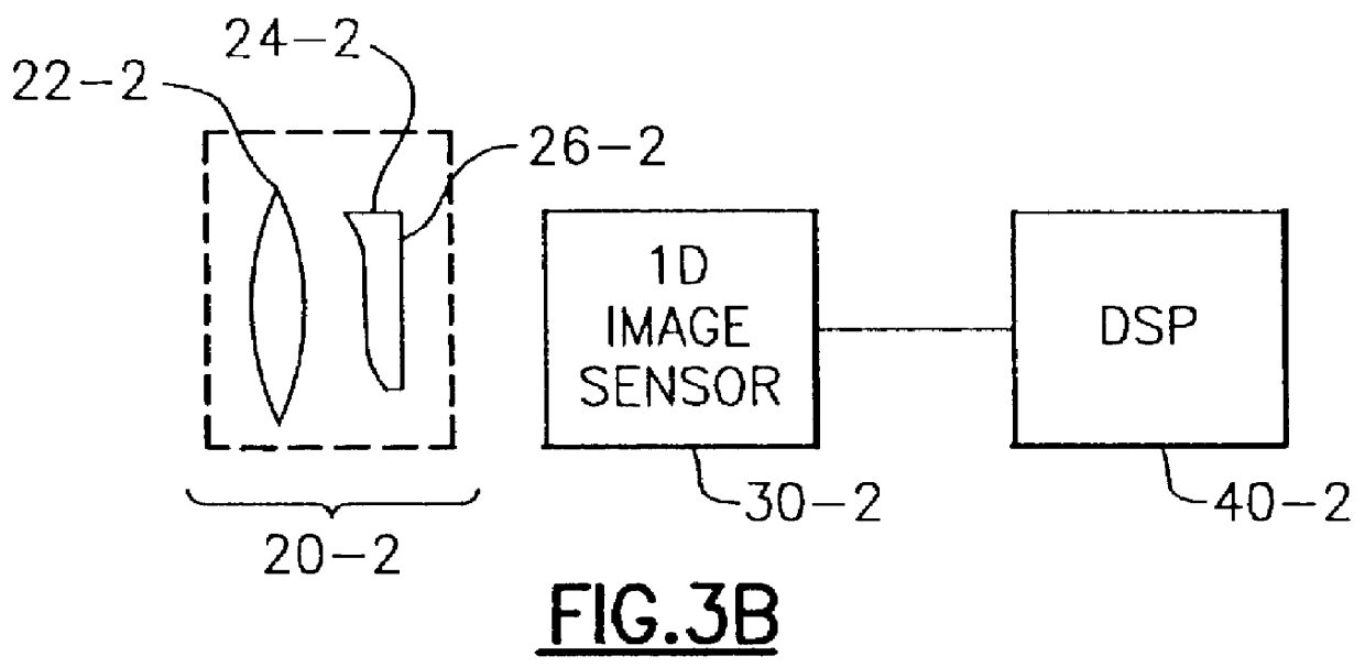
Referring to FIG. 3B there is shown a 1D imaging system constructed in accordance with the invention. The embodiment of FIG. 3B differs from that of FIG. 3A primarily in that its phase mask 24-2 is located at the rear rather than the front principal plane of its lens 22-2. In addition, the amplitude mask 26-2 of the imaging system of FIG. 3B takes the form of a film deposited on the rear surface of phase mask 24-2. Because the statements made in connection with the embodiment of FIG. 3A are equally applicable to the embodiment of FIG. 3B, the embodiment of FIG. 3B will not be discussed in detail herein.

As will be appreciated by those skilled in the art, it is the 1D character of image sensor 30-1 or 30-2 that is responsible for the fact that the imaging systems of FIGS. 3A and 3B are termed 1D imaging systems. As a result, in spite of the fact that the imaging systems of FIGS. 3A and 3B are 1D imaging systems, optical assemblies 20-1 and 20-2 may be constructed using either 1D or 2D...


PUM


Abstract

An improved opto-electronic imaging system which is adapted for use with incoherently illuminated objects, and which produces final images having a reduced imaging error content. The imaging system includes an optical assembly for forming an intermediate image of the object to be imaged, an image sensor for receiving the intermediate image and producing an intermediate image signal, and processing means for processing the intermediate image signal to produce a final image signal having a reduced imaging error content. A reduction in imaging error content is achieved, in part, by including in the optical assembly a phase mask for causing the OTF of the optical assembly to be relatively invariant over a range of working distances, and an amplitude mask having a transmittance that decreases continuously as a function of distance from the center thereof. The reduction in imaging error content is also achieved, in part, by including in the processing means an improved generalized recovery function that varies in accordance with at least the non-ideal calculated IOTF of the optical assembly under a condition of approximately optimum focus.

Description

This invention relates to an improved apparatus and method for reducing the magnitude of misfocus error in an opto-electronic system used for imaging incoherently illuminated indicia, and is directed more particularly to an apparatus and method in which the magnitude of such errors is reduced by the use of an improved optical assembly in combination with digital post-processing utilizing an improved, generalized recovery function.DESCRIPTION OF THE PRIOR ARTObtaining images that are free of errors and distortions introduced by the optical elements that are used in the imaging process has long been a goal of those working with imaging systems. Such systems contemplate the imaging of various kinds of objects, including but not limited to bar code symbols, alphanumeric and non-alphanumeric characters and symbols, and blocks of text. For convenience, all such objects will be referred to herein as target objects or indicia, whether they include encoded data or not. The errors and distort...

Claims


Application Information

Patent Timeline
IPC IPC(8): G06T5/00H04N1/409G02B27/00
CPCG02B27/0075H04N1/4092G06T5/003G06T2207/20192
Inventor HAMMOND, JR., CHARLES MITCHELL
Owner HAND HELD PRODS
Why Eureka
Try Eureka