Heat pump, housing and method

a heat pump and housing technology, applied in the field of wall-mounted, plastic heat pump housings, can solve the problems of insufficient heat generation of the space, inability to provide heat generation means, bulky, weighty or otherwise undesirable, etc., and achieve the effect of reducing weight and space efficien

Inactive Publication Date: 2000-08-08
FRIEDRICH AIR CONDITIONING
View PDF22 Cites 32 Cited by
  • Summary
  • Abstract
  • Description
  • Claims
  • Application Information

AI Technical Summary

Benefits of technology

With the above concerns in mind, it is an objective of the present invention to provide a wall mounted heat pump which is space efficient.
It is a further objective of the present invention to provide a heat pump with a plastic structural foam housing to eliminate the need for extra insulation and to reduce weight.

Problems solved by technology

Some solutions were seen in window mounted air conditioners, but these failed to provide means to heat the space.
While conventional heat pumps allow the heating and cooling functions desired, most are bulky, weighty or otherwise undesirable.
Additionally, most heat pumps are housed in a fabricated metal housing which may have sharp edges and require additional insulation to function properly.

Method used


Image

  • Heat pump, housing and method
  • Heat pump, housing and method
  • Heat pump, housing and method

Examples


Embodiment Construction

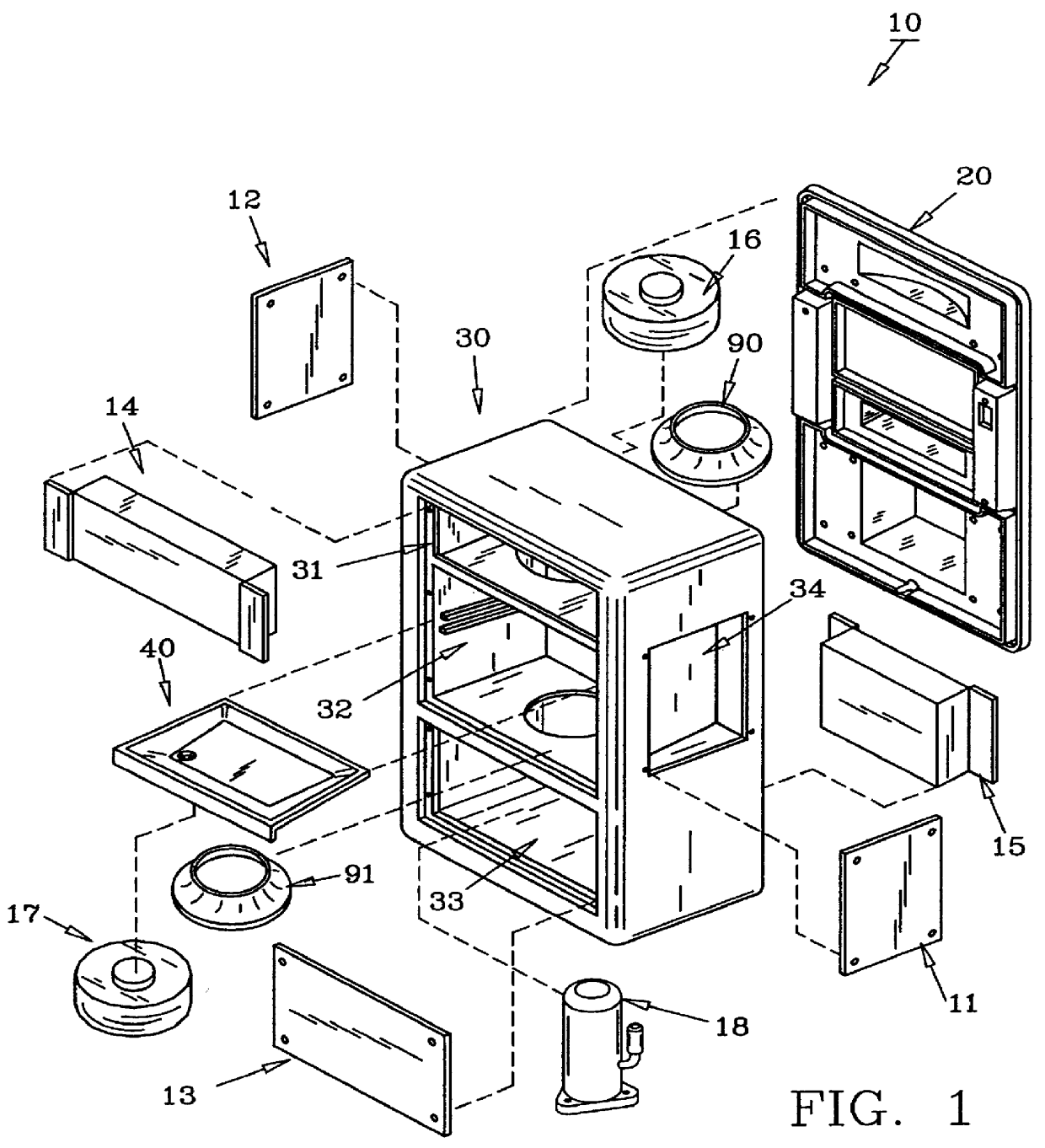
Turning now to the drawings, specifically FIG. 1 shows exploded heat pump 10, which comprises housing wall plate 20, shell 30, side access panels 11 and 12, front access panel 13, front coil 14, back coil 15, removable shelf 40, blowers 16 and 17, inlet rings 90 and 91 and compressor 18. Conventional centrifugal fan, namely first blower 16 is positioned in first or upper chamber 31 to process conditioned air while second blower 17 is mounted in second or lower chamber 32 to process unconditioned air. Compressor 18 is located in third or lowest chamber 33. Side access panels 11 and 12 allow access to electrical chamber 34 and utility chamber 35 (FIG. 3) respectively. Access panels 11-13 and coils 14 and 15 are held on shell 30 by conventional fasteners such as screws, bolts or rivets, although selectively removable fasteners like bolts are preferred. Additional conventional electrical circuitry, refrigerant tubes, plumbing connections and the like are not shown, but well understood i...


PUM


Abstract

A heat pump housing made from plastic is disclosed herein. The housing is preferably two-piece including a wall plate and a shell. The wall plate may be secured to conventional wall studs and provides outside air intake and exhaust openings. The wall plate additionally provides supports for the temporary support of the shell while the shell is being secured to the wall plate. The shell includes chambers for conditioned and unconditioned air, a removable drain shelf separating the two; and shelves for support of the compressor, blowers and other conventional heat pump features.

Description

1. Field of the InventionThis invention pertains to a wall mounted, plastic heat pump housing for use in small rooms or suites.2. Description of the Prior Art and Objectives of the InventionAs hotels and studio apartments have proliferated, there has been a need felt by the HVAC community for a small heating and cooling unit which can handle small volumes of air independently of similarly situated rooms, suites or apartments. Some solutions were seen in window mounted air conditioners, but these failed to provide means to heat the space. Electric space heaters provided another half solution.Another concern in the creation of a solution to the problem is the availability of space. In a studio apartment, space is typically a premium, as in a hotel suite or room. Therefore, any solution must also be space efficient and include both heating and cooling modes.While conventional heat pumps allow the heating and cooling functions desired, most are bulky, weighty or otherwise undesirable. M...

Claims


Application Information

Patent Timeline
Patent Type & Authority Patents(United States)
IPC IPC(8): F24F1/02F24F13/02F24H9/02F25B30/02F25B30/00
CPCF24F1/022F24F13/0254F24H9/02F25B30/02
Inventor ADDINGTON, ROBERT R.NEWSOM, BOBBY G.
Owner FRIEDRICH AIR CONDITIONING
Why Eureka
Try Eureka