Fuel injection method and device for engines

a technology for fuel injection and engines, applied in the direction of electrical control, process and machine control, instruments, etc., can solve the problems of engine vibration, deterioration of exhaust emission performance, response delay present in the drive circuit,

Inactive Publication Date: 2000-08-15
ISUZU MOTORS LTD
View PDF7 Cites 54 Cited by
  • Summary
  • Abstract
  • Description
  • Claims
  • Application Information

AI Technical Summary

Problems solved by technology

This time lag results from a response delay present in a drive circuit, i.e., a delay after the command pulse has been issued from the controller to the solenoid until the solenoid is actually energized, and a mechanical delay after the solenoid has been energized to lift the needle valve until the fuel is injected from the nozzle holes.
Hence, changes over time of the time lag and variations among individual injectors combine to prevent optimum combustion of fuel, causing deterioration of the exhaust emission performance and also engine vibrations due to differences in the combustion timing among cylinders.
The above-described method and device for detecting the fuel injection timing, however, concerns a fuel injection system using a distribu

Method used


Image

  • Fuel injection method and device for engines
  • Fuel injection method and device for engines
  • Fuel injection method and device for engines

Examples


Embodiment Construction

Now, by referring to the accompanying drawings, embodiments of the fuel injection method and device for engines according to this invention will be described.

The common-rail type fuel injection system shown in FIG. 7 may be used as a fuel injection system for this invention. The constitutional elements of this system are assigned the same reference numerals as those shown in FIG. 7 and their repetitive explanations are omitted.

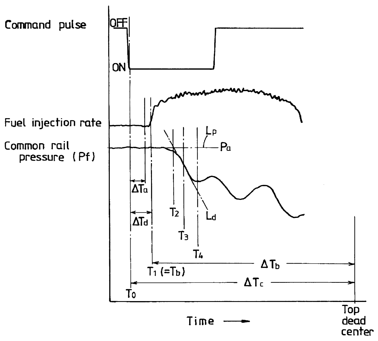
Changes over time of the command pulse, the fuel injection rate and the common rail pressure will be explained by referring to the graph of FIG. 1.

In each cylinder n, when the command pulse is turned on at a time T.sub.0 (the time at which an injection command signal is issued) before a top dead center, the injector 1 starts injecting fuel with a delay time .DELTA.Td at a fuel injection time T.sub.1. The actual pressure Pf of the common rail 2 (common rail pressure) does not fall immediately after the fuel injection from the injector 1 has started but starts f...


PUM


Abstract

This invention determines the output timing of the injection command signal to each of the injectors so that the fuel injection timing agrees with the basic target injection timing even when there are variations in the fuel injection timing among the injectors, and thereby improves the exhaust emission performance of the engine. The time T2 of an intersection between the straight line Lp representing an average Pa of the common rail pressure before it starts to fall and the first-degree approximation straight line Ld having a maximum inclination of fall of the common rail pressure is determined as the timing at which the common rail pressure starts to fall. Based on the time T2 and the average pressure Pa, the delay time DELTA Td which elapses from the output timing T0 of the injection command signal to each of the injectors to the actual fuel injection timing T1 is calculated. The output timing T0 for the injection command signal is determined as an instant the delay time DELTA Td before the basic target injection timing Tb, which is determined from the operating state.

Description

1. Field of the InventionThe present invention relates to a fuel injection method and device for engines which receives fuel from a common rail and injects the fuel from injectors into combustion chambers.2. Description of the Prior ArtAs for the fuel injection control in engines such as diesel engines, a common-rail type fuel injection system has been known which provides a high injection pressure and performs optimum control on the injection characteristics, such as fuel injection timing and the amount of fuel injected, according to the operating condition of the engine. The common-rail type fuel injection system stores in the common rail a fuel pressurized to a predetermined pressure by a fuel pump and then injects the stored fuel from injectors into corresponding combustion chambers. A controller controls the fuel pressure in the common rail and the operation of control valves for the injectors so that the pressurized fuel will be injected from each injector under optimum inject...

Claims


Application Information

Patent Timeline
IPC IPC(8): F02D41/38F02D41/40F02B3/06F02B3/00F02M55/02
CPCF02D41/3827F02D41/401F02B3/06F02D2250/31Y02T10/44Y02T10/40
Inventor NISHIYAMA, YASUHIRO
Owner ISUZU MOTORS LTD
Why Eureka
Try Eureka