System and method for oxidant injection in rotary kilns

a technology of rotary kilns and oxidants, which is applied in the field of new products, can solve the problems of unavailability, inability to meet the needs of customers,

Inactive Publication Date: 2000-09-12
LAIR LIQUIDE SOCITE ANONYME POUR LETUD & LEXPL DES PROCEDES GEORCLAUDE +1
View PDF10 Cites 91 Cited by
  • Summary
  • Abstract
  • Description
  • Claims
  • Application Information

AI Technical Summary

Problems solved by technology

Experimental work was done in Germany in the 1940's, but results are not available.
Increasing the oxygen concentration may lead to potential safety problems, since the fuel is in contact with the O.sub.2 enriched air prior to its arrival into the kiln's combustion space, and therefore can burn too early, or explode.
The use of oxygen lances, although a more elegant solution, can locally increase the temperature of the combustion space, which can result in non-uniform heat transfer to the entire flow of clinkers moving through the kiln.
Oxygen lances can produce hot spots in the refractory, which may damage the refractory.
Further, the introduction of cold oxygen may limit the beneficial effect of oxygen on combustion by locally cooling the flame.
This device suffers from a number of significant problems, including the difficulty of creating a leak-free plenum which rotates with the kiln and the difficulty of installing tubes into the kiln.
Additionally, the procedure disclosed in the '829 patent suffers from certain inherent drawbacks.
Nitrogen does not facilitate combustion, and thus represents an unproductive use of flue gas volume.
Excessive nitrogen content may result in additional dust generation and may significantly increase the amount of nitrous oxide (NO.sub.x) emissions.
Also, the injection of cold ambient air may reduce the thermal efficiency of the kiln and may cause additional stresses in the rotary kiln which can damage its expensive structure from thermal shock.

Method used


Image

  • System and method for oxidant injection in rotary kilns
  • System and method for oxidant injection in rotary kilns
  • System and method for oxidant injection in rotary kilns

Examples


Embodiment Construction

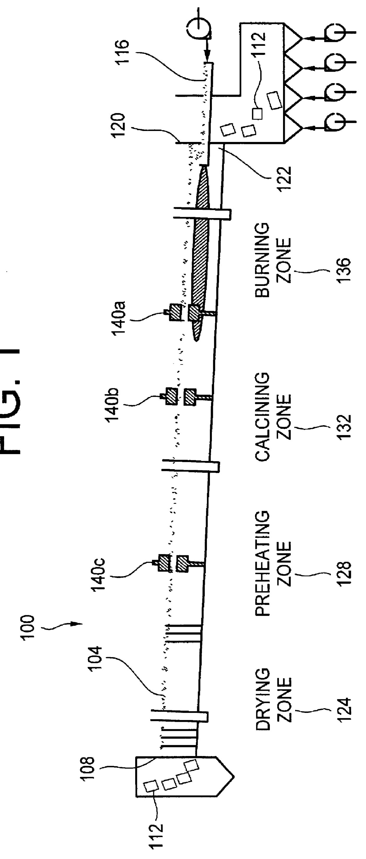
FIG. 1 is a schematic illustration of a rotary kiln in accordance with an embodiment of the present invention. Referring to FIG. 1, rotary kiln 100 includes a substantially cylindrical kiln body 104 rotatable about a longitudinal axis extending along its length. Kiln body 104 has an opening at a first end 108 for receiving raw material, commonly referred to in the art as raw "clinker" material 112, or "clinkers." The raw clinker material is conveyed along the floor of kiln body 104 and subjected to heat from burner 116 positioned proximate second end 120 of kiln body 104. Clinkers 112 are passed through an opening 122 in second end 120 of kiln body 104, whereupon they may be subjected to further treatment, if necessary.

It is common in the art to refer to kiln body 104 as having a plurality of zones. The zones may be designated as a drying zone 124 in which moisture is removed from raw clinker material 112, a preheating zone 128 in which the raw clinker material 112 is heated, typica...


PUM


Abstract

A system and method for increasing the amount of oxygen in a kiln chamber is disclosed. The radial surface of a rotatable kiln is provided with at least one oxidant injection port extending through the radial surface into the kiln chamber. A cam is connected to the radial surface adjacent the oxidant injection port. A valve assembly including a valve chamber in fluid communication with an oxidant supply is mounted adjacent the kiln substantially in fixed spatial relation with the rotatable kiln body. The valve assembly includes a follower member adapted to contact a surface to the cam to actuate the valve assembly. Rotation of the kiln body brings the cam into contact with the follower member, thereby actuating the oxidant injection assembly, and injecting oxidant through the injection port into the kiln chamber.

Description

1. Field of the InventionThe present invention relates to novel apparatus and processes for the injection of an oxidant into a rotary kiln. More particularly, the present invention relates to apparatus and processes which significantly improve combustion in a rotary kiln used for the calcination of minerals such as cement, lime, dolomite, magnesia, titanium dioxide, and other calcined materials.2. Brief Description of the Related ArtThe introduction of oxygen into a combustion space, e.g., a furnace, is used in a variety of industries for enhancement of the combustion process. The general use of oxygen in cement rotary kilns has been shown to lead to a significant production increase of the kiln, starting with the work of Gaydas, R. A., "Oxygen enrichment of combustion air in rotary kilns," Journal of the PCA R & D Laboratories, 49-66 (September 1965) (incorporated by reference in its entirety herein). Gaydas presents test results from a period between 1960 and 1962. It is noted tha...

Claims


Application Information

Patent Timeline
Patent Type & Authority Patents(United States)
IPC IPC(8): F27B7/00F27B7/16F27B7/34F27B7/20F27B7/36
CPCF27B7/161F27B7/20F27B7/34F27B2007/367
Inventor JOSHI, MAHENDRA L.MARIN, OVIDIUCHARON, OLIVIERDUGUE, JACQUES
Owner LAIR LIQUIDE SOCITE ANONYME POUR LETUD & LEXPL DES PROCEDES GEORCLAUDE
Why Eureka
Try Eureka