Combustion powered cooling system

a cooling system and vapor compression technology, applied in the direction of machines/engines, lighting and heating apparatus, heat pumps, etc., can solve the problems of limited effectiveness, increased electrical power consumption of air conditioning systems, and operator's incurring higher costs of electrically powered vapor compression air conditioning systems and gas fired heating systems, etc., to achieve greater reliability, high efficiency, and economical production and operation.

Inactive Publication Date: 2000-10-31
APPLIED POWER TECH
View PDF3 Cites 19 Cited by
  • Summary
  • Abstract
  • Description
  • Claims
  • Application Information

AI Technical Summary

Benefits of technology

It is a further object of the present invention to provide a combustion powered cooling system that has higher efficiency.
It is a further object of the present invention to provide a combu...

Problems solved by technology

A limitation of some types of heat transfer systems that include heat pumps is that they are of limited effectiveness when outside temperatures are low.
This results in an operator incurring higher costs for...

Method used


Image

  • Combustion powered cooling system
  • Combustion powered cooling system
  • Combustion powered cooling system

Examples


Embodiment Construction

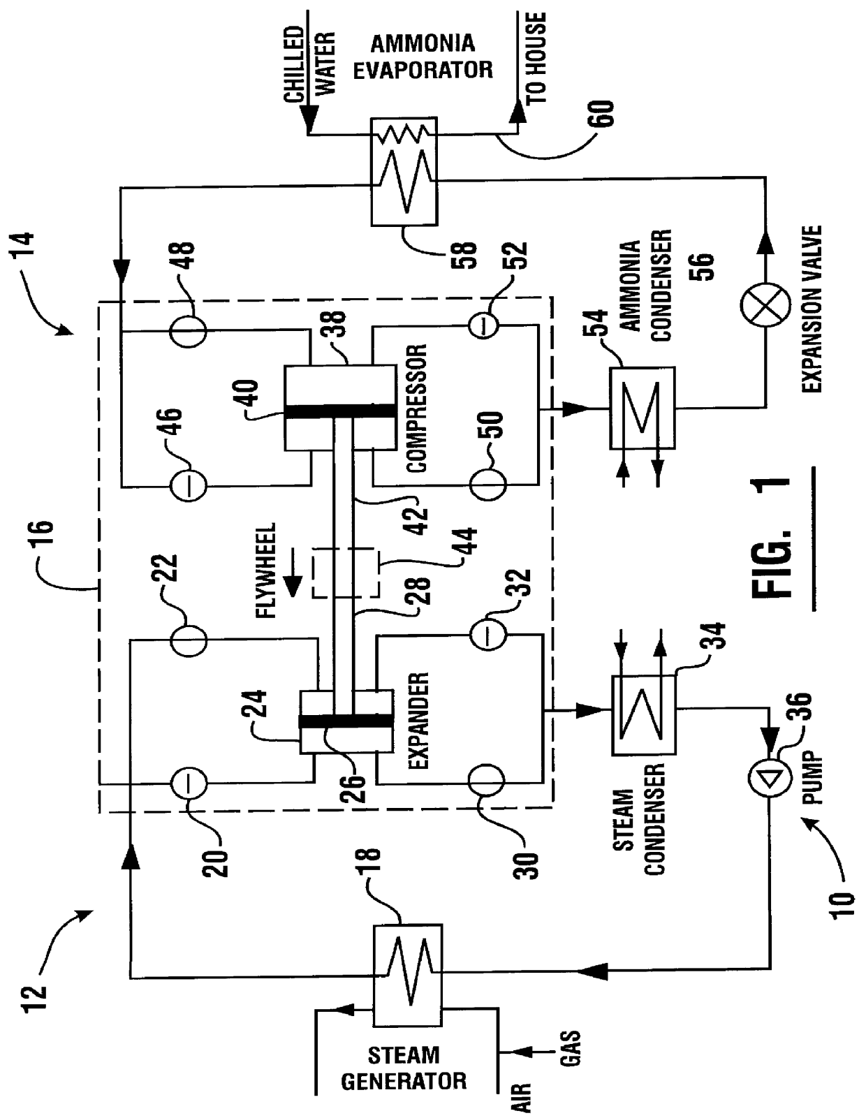
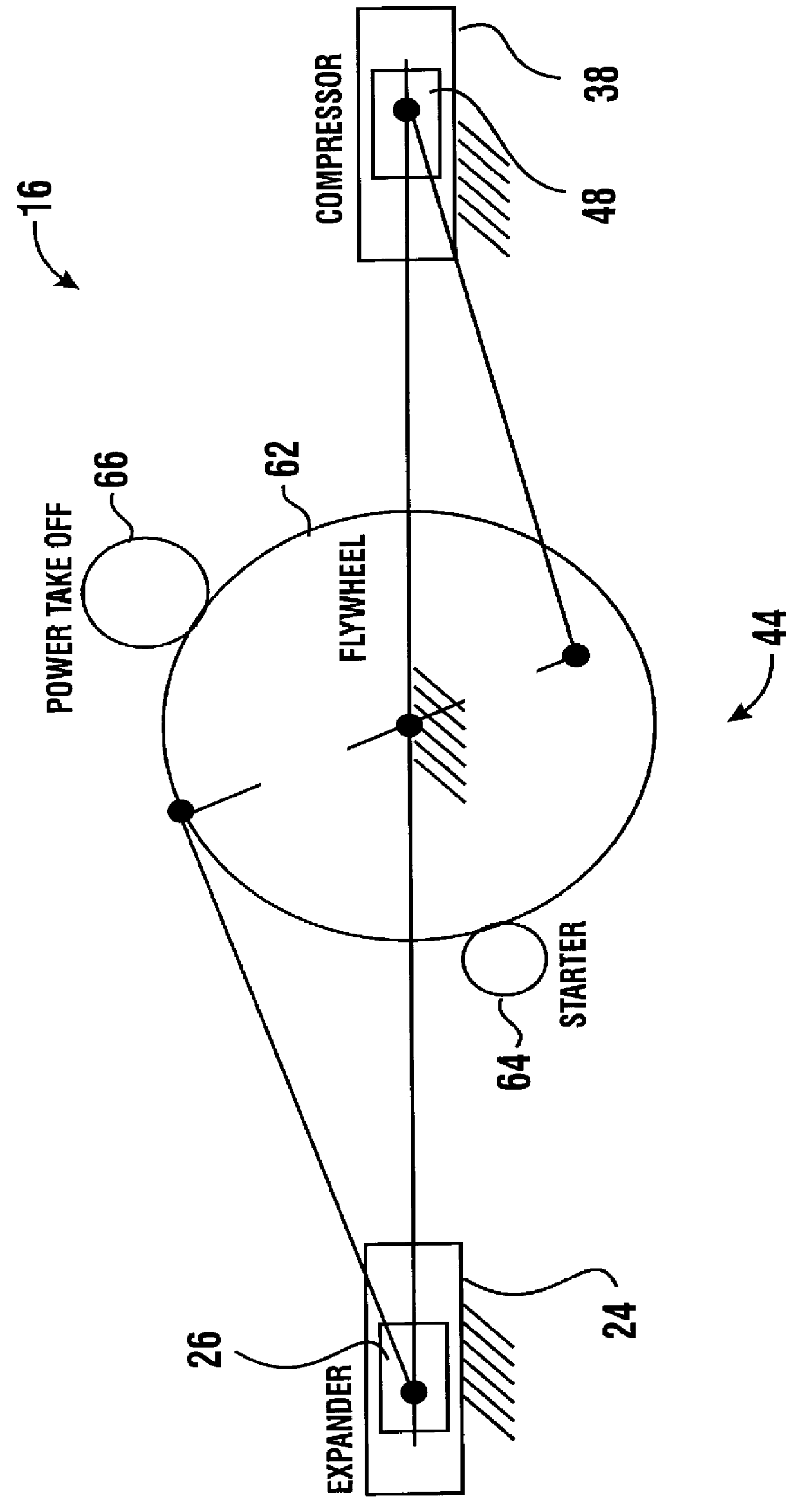
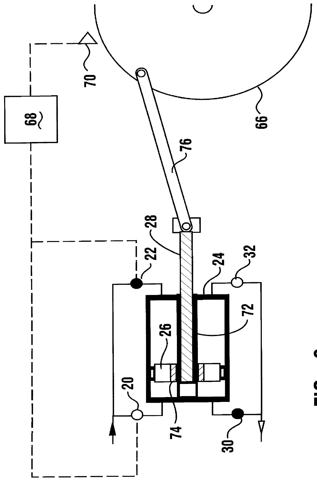
Referring now to the drawings and particularly to FIG. 1, there is shown therein a first embodiment of the combustion powered cooling system of the present invention generally indicated 10. System 10 includes a power loop 12 and a cooling loop 14. A power unit schematically indicated 16 operates to transfer energy from the power loop to the cooling loop.

The power loop has a first working fluid therein. In the preferred form of the invention the first working fluid is water. However, in alternate embodiments the first working fluid is an organic refrigerant and has good lubricating properties. The water in the power loop 12 is heated to produce superheated steam in a steam generator 18. As later described in detail the steam generator operates in the preferred embodiment to produce heat by combustion of a mixture of air and natural gas. The heat produced by combustion is transferred to the water in the power loop.

The superheated steam from the steam generator 18 is passed to the powe...


PUM


Abstract

A combustion powered cooling system (10, 100) includes a power loop (12, 102) and a cooling loop (14, 104). Heat produced by combustion is used to produce superheated steam in a steam generator (18). The steam is used to move a reciprocating steam piston (26) in a power unit (16). Power is transferred from the steam piston through a energy transfer mechanism (44) to a compressor piston (40) in the cooling loop. Refrigerant material in the cooling loop is used to provide air conditioning for a residence or other facility through a chilled water circuit (60). The system is also operative as a heat pump for heating a residence or other facility.

Description

This invention relates to heat transfer systems. Specifically this invention relates to a combustion powered cooling system, such as an air conditioning system powered by natural gas.Numerous types of heat transfer systems have been developed. Prior systems include vapor compression type heat pump systems which may be used for heating and / or cooling an interior area of a structure or water housed in a pool or other reservoir. Such prior systems have most often been powered electrically. Other systems have been powered by combustion processes such as the systems shown in U.S. Pat. Nos. 5,509,274; 5,313,874; 5,246,350; and 5,205,133.In the development of combustion powered heat transfer systems advances are constantly sought. Increases in heat transfer capacity and energy efficiency are always desired. Other areas in which improvements in such systems are desirable include reliability, cost of equipment and cost of operation.A limitation of some types of heat transfer systems that inc...

Claims


Application Information

Patent Timeline
IPC IPC(8): F01B17/04F01B17/00F22B27/08F22B27/00F22B21/00F22B21/06F22B27/16F28D7/10F25B27/00F25B30/06F25B30/00
CPCF01B17/04F22B21/065F22B27/08F28D7/106F25B27/00F22B27/16F25B30/06
Inventor LACKSTROM, DAVIDDE TREVILLE, THOMAS B.
Owner APPLIED POWER TECH
Why Eureka
Try Eureka