Non-Radiative dielectric line assembly

a dielectric line and non-radiative technology, applied in the field of electronic parts, can solve the problems of inability to design a bend having an arbitrary radius of curvature, and the whole cannot be miniaturized, and achieve the effect of excellent characteristi

Inactive Publication Date: 2000-11-07
MURATA MFG CO LTD
View PDF5 Cites 12 Cited by
  • Summary
  • Abstract
  • Description
  • Claims
  • Application Information

AI Technical Summary

Benefits of technology

It is another object of the present invention to provide an integrated circuit of a non radiative dielectric line part having an excellent characteristic, with utilizing the respective characteristics of the normal NRD guide and the hyper NRD guide.

Problems solved by technology

On one hand, in the normal NRD guide as mentioned above, there has been a problem such that since a transmission loss is occurred by a mode transformation of the LSM01 mode and the LSE01 mode in a bend part, it makes it impossible to design a bend having an arbitrary radius of curvature, and for preventing the transmission loss by the above mentioned mode transformation, the radius of curvature in the bend part can rot be made smaller, thereby the module as a whole can not be miniaturized.

Method used


Image

  • Non-Radiative dielectric line assembly
  • Non-Radiative dielectric line assembly
  • Non-Radiative dielectric line assembly

Examples


Embodiment Construction

Referring to FIGS. 1 to 13, a configuration of a millimeter radar module that is an embodiment of the present invention will be described in detail.

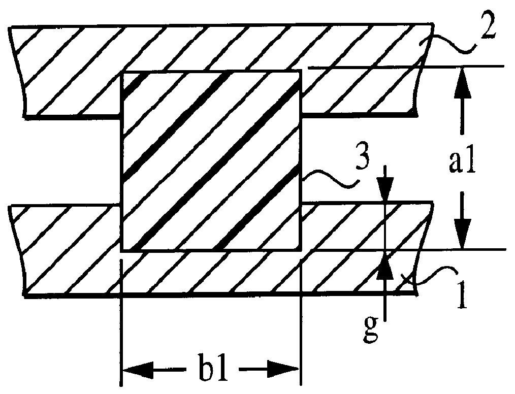
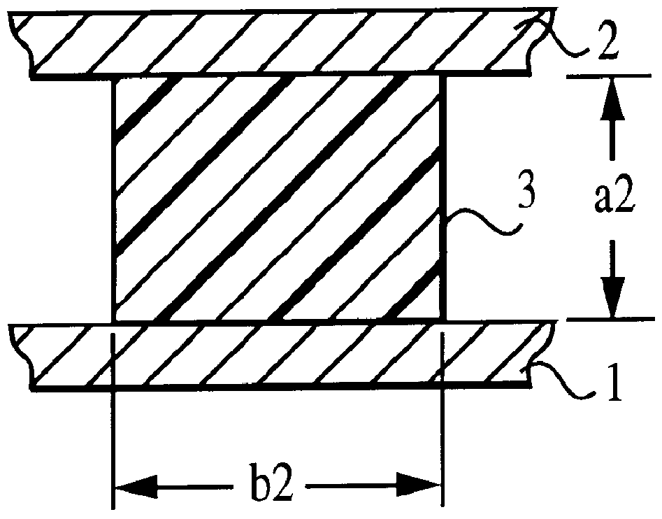
As already described above, FIG. 1 is a cross-sectional view of the hyper NRD guide part, FIG. 2 is a cross-sectional view of the normal NRD guide part. In either NRD guide, a dielectric strip 3 is placed between two conductor plates 1, 2 of the upper and lower. In the normal NRD guide shown in FIG. 2, the height dimension a2 of the dielectric strip 3 is equal to a space between the conductor plates 1, 2, but in the hyper NRD guide shown in FIG. 1, a groove with a depth g is respectively formed in the conductor plates 1, 2, so that a space between the conductor plates 1, 2 in the area where there is no dielectric strip 3 is made shorter than the height dimension a1 of the dielectric strip 3, thereby the area where there is the dielectric strip is set to be a propagation area where a single mode of the LSM01 propagates.

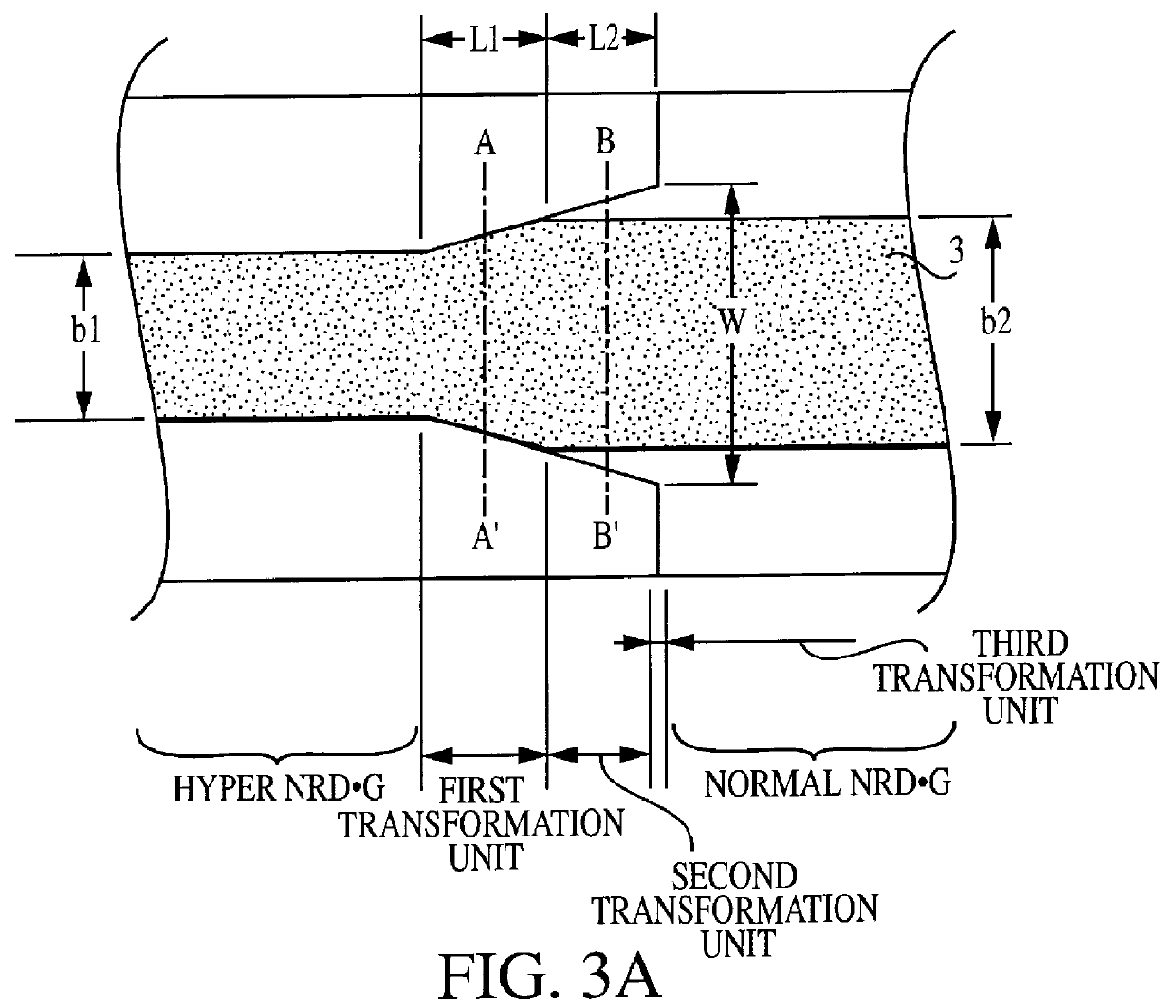
FIGS. 3A to 3C are ...


PUM


Abstract

A normal NRD guide is constituted in the part to be coupled with a dielectric resonator, a hyper NRD guide for simply transmitting the LSM01 mode is constituted in a multipoints circulator part, the normal NRD guide is constituted in a coupler part, the hyper NRD guide is constituted in the mixer part, and the normal NRD guides are constituted in a dielectric line switch part and in a connection unit between components.

Description

1. Field of the InventionThe present invention relates to an electronic part. More particularly, the present invention relates to an electronic part having a non radiative dielectric waveguide and integrated circuit using the same which are used in a microwave or millimeter-wave radar for example.2. Description of the Related ArtAs shown in FIG. 2, a conventional transmission line for a millimeter wave or a micrometer wave, has two parallely opposing conductive plates 1, 2 and a dielectric strip 3 disposed between the conductive plates. A normal type non radiative dielectric waveguide ("normal NRD") is a kind of transmission line. The distance a2 between the conductive plates is adjusted to be equal to or less than a half wavelength of a wavelength of an electromagnetic wave so that the electromagnetic wave propagates only in the strip line 3.A millimeter wave module that uses tie NRD guide is constituted by integrating each of the components, such as an oscillator, a mixer, and a c...

Claims


Application Information

Patent Timeline
Patent Type & Authority Patents(United States)
IPC IPC(8): H01P3/16H01P5/08H01P3/00H01P1/12H01P1/383H01P1/04H01P5/02H01P5/18H03D9/06
CPCH01P5/087H01P3/165H01P7/10H01P5/18
Inventor SAITOH, ATSUSHITANIZAKI, TORUNISHIDA, HIROSHITAKAKUWA, IKUOTAGUCHI, YOSHINORI
Owner MURATA MFG CO LTD
Why Eureka
Try Eureka