Dual orifice bypass system for dual-fuel gas turbine

a dual-fuel gas turbine and bypass system technology, which is applied in the direction of machines/engines, mechanical equipment, light and heating apparatus, etc., can solve the problems of reducing the affecting the cooling efficiency of the cooling system, so as to reduce the flow of cooling water, prevent over-cooling, and reduce the flow of cooling medium

Inactive Publication Date: 2000-11-14
GENERAL ELECTRIC CO
View PDF8 Cites 159 Cited by
  • Summary
  • Abstract
  • Description
  • Claims
  • Application Information

AI Technical Summary

Benefits of technology

In accordance with the present invention, there is provided a staged dual bypass system in conjunction with a temperature responsive flow control valve which satisfies the requirements of both atomizing air and purge modes of operation, while employing a single heat exchanger. To accomplish this, the flow of cooling medium, e.g., water, is controlled as in the previously disclosed conventional system by a temperature regulating valve responsive to the temperature of the compressor discharge air exiting the heat exchanger. In contrast, however, a pair of passages bypassing the temperature regulating valve are provided, each passage having an orifice. The orifice restriction in a first bypass passage is sized to enable flow of the cooling water through the heat exchanger during operation in a purge mode when the temperature regulating valve is closed. This affords a reduced flow of cooling medium through the heat exchanger for cooling the compressor discharge air to approximately 225.degree. F. and, consequently, prevents over-cooling. That is, this first bypass passage with the orifice restriction is sized for purge mode operation and, consequently, the reduced flow of cooling water through the heat exchanger is able to maintain the temperature of the compressor discharge air exiting the heat exchanger at approximately 225.degree. F. In the atomizing air mode, a bypass isolation valve in the second bypass passage is opened. Should the temperature regulating valve close in response to low ambient inlet cooling water temperature and hence decreased air temperature exiting the heat exchanger, the two bypass passages in the atomizing air mode afford a minimum protective cooling water flow through the heat exchanger to prevent heat build-up in the cooling water in the heat exchanger which could damage the heat exchanger and require shutdown of the turbine. The orifices in the two bypass passages are thus sized for the worst-case scenario in the atomizing air mode. Consequently, the staged dual bypass system hereof satisfies the performance requirements of two distinct system operating mode heat rejections while using a single heat exchanger.
In a further preferred embodiment according to the present invention, there is provided a method of controlling the temperature of compressor discharge air in a dual-fuel gas turbine having gas and liquid fuel operating modes, comprising the steps of passing the compressor discharge air in heat exchange relation with a cooling medium having an inlet temperature to the heat exchanger lower than the temperature of the compressor discharge air, controlling the flow of the cooling medium through the heat exchanger to regulate the temperature of the compressor discharge air exiting the heat exchanger, maintaining a minimum flow of cooling medium through the heat exchanger when operating the gas turbine in the liquid fuel mode and reducing the flow of cooling medium through the heat exchanger to a flow below the minimum flow when operating the gas turbine in the gas fuel mode.

Problems solved by technology

Should the ambient temperature of the cooling water, however, be low, for example, when using cooling water supplied during winter conditions, the reduction in water flow can cause the water to boil in the heat exchanger.
This, in turn, can result in damage to the heat exchanger and cause a shutdown of the turbine.
Over-cooling the discharge air disadvantageously produces increased condensation which must be eliminated and otherwise compromises the system.
The problem of not being able to reduce the water flow sufficiently at lower ambient water inlet temperatures to the heat exchanger is exacerbated when the system is operated in the purge mode rather than in the atomizing air mode.
Because the heat exchanger is sized for the maximum heat rejection at maximum cooling water temperature, the desired compressor discharge air temperature of 225.degree. F. becomes impossible to maintain at minimum heat rejection and low ambient cooling water inlet temperature conditions, resulting in over-cooling of the compressor discharge air.

Method used


Image

  • Dual orifice bypass system for dual-fuel gas turbine
  • Dual orifice bypass system for dual-fuel gas turbine
  • Dual orifice bypass system for dual-fuel gas turbine

Examples


Embodiment Construction

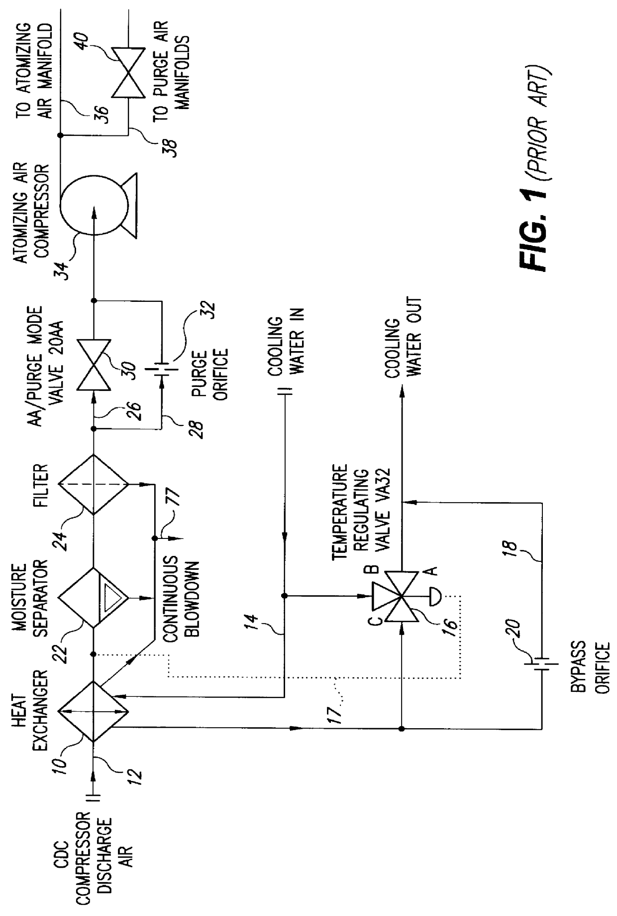
Referring to the prior art system of FIG. 1, there is schematically illustrated a heat exchanger 10 having compressor discharge air and cooling medium, e.g., water, inlets 12 and 14, respectively, for heat exchange between the two mediums whereby the compressor discharge air temperature can be reduced from approximately 800.degree. F. to about 225.degree. F. To accomplish this, the flow of the cooling medium through the heat exchanger is controlled by a temperature regulating valve 16 responsive to the temperature of the compressor discharge air exiting the heat exchanger 10, as indicated by the dotted line 17 in FIG. 1. That is, as the temperature of the air exiting heat exchanger 10 rises above or falls below the desired temperature, the flow of cooling medium is increased or reduced, respectively. Heat exchanger 10 may be a parallel flow or counterflow heat exchanger. In either case, the temperature of the compressor discharge air is maintained at a predetermined temperature at t...


PUM


Abstract

Compressor discharge air flows through a heat exchanger in heat exchange relation with cooling water and is supplied at reduced temperature in atomizing air and purge modes to combustors in a dual-fuel gas turbine. The heat exchanger has a pair of bypass passages in parallel with a temperature regulating valve controlling flow of water through the heat exchanger in response to the temperature of the compressor discharge air exiting the heat exchanger. Should the flow control valve close in response to low temperature of the compressor discharge air, in the air atomizing mode, the bypass passages with orifices therein provide a minimum protective flow of cooling water to the heat exchanger. In the purge mode where only half the air flow and heat rejection is required in the heat exchanger and the flow control valve closes, a bypass valve in one of the bypass passages closes to enable reduced flow of cooling water through the heat exchanger.

Description

TECHNICAL FIELDThe present invention relates to a system for controlling the temperature of compressor discharge air in a dual-fuel gas turbine and particularly relates to a staged dual bypass system for controlling the temperature of the compressor discharge air for both liquid fuel and gas fuel operations, requiring two distinct heat rejection modes while using a single heat exchanger.BACKGROUND OF THE INVENTIONIn dual-fuel gas turbines, the turbine operates by burning either a gaseous fuel or a liquid fuel, the latter fuel being typically distillate oil. Whenever burning one fuel, the nozzles for the other fuel must be continuously purged. For example, when gaseous fuel is burned in the turbine combustors, the liquid fuel, atomizing air and water injection nozzles of the combustors are purged using cooled compressor discharge air. When burning liquid fuel, atomizing air is supplied to the combustor for atomizing the liquid fuel, while the gas fuel nozzles are purged using compres...

Claims


Application Information

Patent Timeline
Patent Type & Authority Patents(United States)
IPC IPC(8): F02C9/28F02C7/08F02C7/16F02C9/00F02C9/18
CPCF02C7/08F02C7/16F02C9/28F02C9/18F05D2270/303F23D2209/30
Inventor KAPLAN, HOWARD JAYSTIMPSON, JOEL THOMAS
Owner GENERAL ELECTRIC CO
Why Eureka
Try Eureka