Process for incinerating solids on a water-cooled thrust combustion grate, and a grate plate and grate for accomplishing the process

a technology of incinerating solids and combustion grates, which is applied in the direction of solid bar grates, combustion process, lighting and heating apparatus, etc., can solve the problems of completely delivering all the oxygen, creating a high darting flame, and irregular air penetration into the combustion bed

Inactive Publication Date: 2000-12-05
DOIKOS INVESTIMENTS LTD
View PDF14 Cites 10 Cited by
  • Summary
  • Abstract
  • Description
  • Claims
  • Application Information

AI Technical Summary

Problems solved by technology

One of the disadvantages of this concept is that the penetration of the combustion bed by the air is very irregular.
Another disadvantage is that, where the calorific value of the combustible material is high and the combustion bed is thin, as occurs repeatedly from spot to spot as the combustible material is transported along the flow of primary air breaks through the combustion bed at that point, creating a high darting flame which carries dust and ash with it far up into the boiler room without completely delivering all the oxygen to the fire.
This causes a local excess of air, which has a negative impact on the flue gas.
One remaining disadvantage, however, is that, especially in the event of high calorific values and/or a combustion bed which is thin from spot to spot, the primary air flow exiting from a primary air duct opening located at such a spot can break through the combustion bed.
Because the composition, and hence the calorific value, and also the volume of, for example, domestic waste fluctuates greatly from region to region and season to season, as do its physical characteristics such as specific weight, article size distribution, permeability to air, moisture, ash content, percentage of non-ferrous metals etc., it is not easy always to achieve good combustion of the combustible gases and s

Method used


Image

  • Process for incinerating solids on a water-cooled thrust combustion grate, and a grate plate and grate for accomplishing the process
  • Process for incinerating solids on a water-cooled thrust combustion grate, and a grate plate and grate for accomplishing the process
  • Process for incinerating solids on a water-cooled thrust combustion grate, and a grate plate and grate for accomplishing the process

Examples


Embodiment Construction

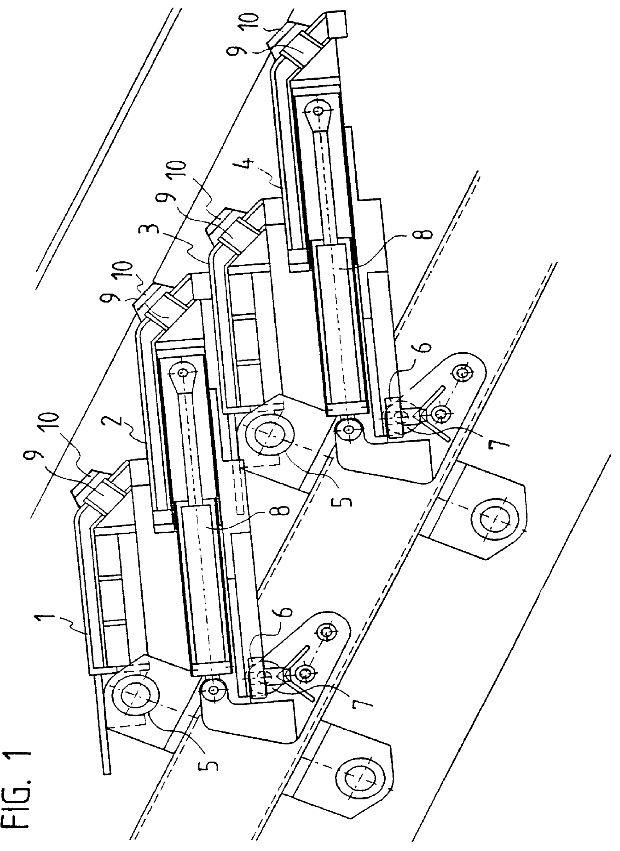
Thrust combustion grates have stationary and movable layers of grates comprising grate plates or a row of grate bars, with the layers of grates resting on top of each other like a stairway. Thrust combustion grates of this kind can be installed in such a way that the combustion bed lies essentially horizontally, or at an angle with angles of up to 20 degrees or more being common. European latent Reference EP 0 621 449 discloses a water-cooled thrust combustion grate with grate plates made from sheet steel which form panel-shaped hollow elements extending over an entire width of the grate path, through which water is directed as a cooling medium. Every second grate plate is movable, and can therefore execute a scraping or a transporting stroke. In the case of a forward feed grate, the leading edge of the movable grate plates can push combustible material forward onto the next grate plate down. In contrast, a reverse feed grate forms something like a sloping stairway built in the wron...


PUM


Abstract

A process wherein primary air supplied to the combustion bed through the thrust combustion grate is deflected after exiting from a surface of the thrust combustion grate by deflector elements mounted on the surface of the thrust combustion grate. The grate required for this purpose has grate plates made from a permeable hollow element with connection pieces for supplying and draining cooling water, with primary air supply ducts that run through the grate plate from a bottom to a top. Deflector elements against which the primary air exiting the outlet is intended to impact, are disposed over openings of the primary air supply ducts.

Description

1. Field of the InventionThis invention relates to a process for incinerating solids on a water-cooled thrust combustion grate of the type installed, for example, in waste incinerators. This invention also relates to a specific grate plate and a grate having of a number of such grate plates for carrying out the process. The solids to be incinerated can be all kinds of different solids, for example lignite, shavings, chips of wood or rubber, residues of all kinds, industrial waste, sewage sludge, hospital waste or domestic refuse, and the like.2. Description of Prior ArtIn the case of conventional thrust combustion grates of the type installed in waste incinerators and which have layers of grates that rest on top of each other in the manner of a stairway, of which every second one can be moved in a thrust direction, primary air is blown from underneath and through the grate and into a combustion bed. In the case of cast grates, which are still the most widely used type of grate, wher...

Claims


Application Information

Patent Timeline
IPC IPC(8): F23H1/00F23H1/02F23H7/00F23L1/02F23L1/00F23H3/00F23H3/02F23H7/08F23G5/00F23G5/44
CPCF23H1/02F23H3/02F23L1/02F23H7/08F23H2900/03021F23G5/002F23H11/12F23H2700/009
Inventor STIEFEL, JAKOB
Owner DOIKOS INVESTIMENTS LTD
Why Eureka
Try Eureka