Self-cooled refrigerant recovery system

Inactive Publication Date: 2000-12-12
SZUTU HUI JEN
View PDF6 Cites 26 Cited by
  • Summary
  • Abstract
  • Description
  • Claims
  • Application Information

AI Technical Summary

Problems solved by technology

Venting refrigerant into our air is no longer allowed.
However, the sincere motivation to comply with the law is frequently failed due to the recovery systems often not doing it job well.
The recovery systems currently available in the industry have two common problems, the recovering speed is too slow and the pressure rapidly build up in the recovery tanks which is up to a dangerous level.
The high pressure in the recovery tank not only slow down the recovery process, it also can be fatal as well to people whom close by if explosion ever occur.
It is legal to vent refrigerants into the air with this manner, but it is not good for our environment.
There are good chances that the refrigerant of an unit being recovered was partially recovered and the rest of the refrigerant remained in the unit was vented into our atmosphere, creating a long-term environmental problem.
It is impossible to completely recover refrigerant if the recovery tank has excessive pressure.
It slows down the recovery speed and the excessive pressure can burst the recovery tank as well.
Refrigerants can not be recovered into the recovery tank if pressure is too high inside the tank; even the tank is not full according to its capacity by weight.
To re

Method used


Image

  • Self-cooled refrigerant recovery system

Examples


Example

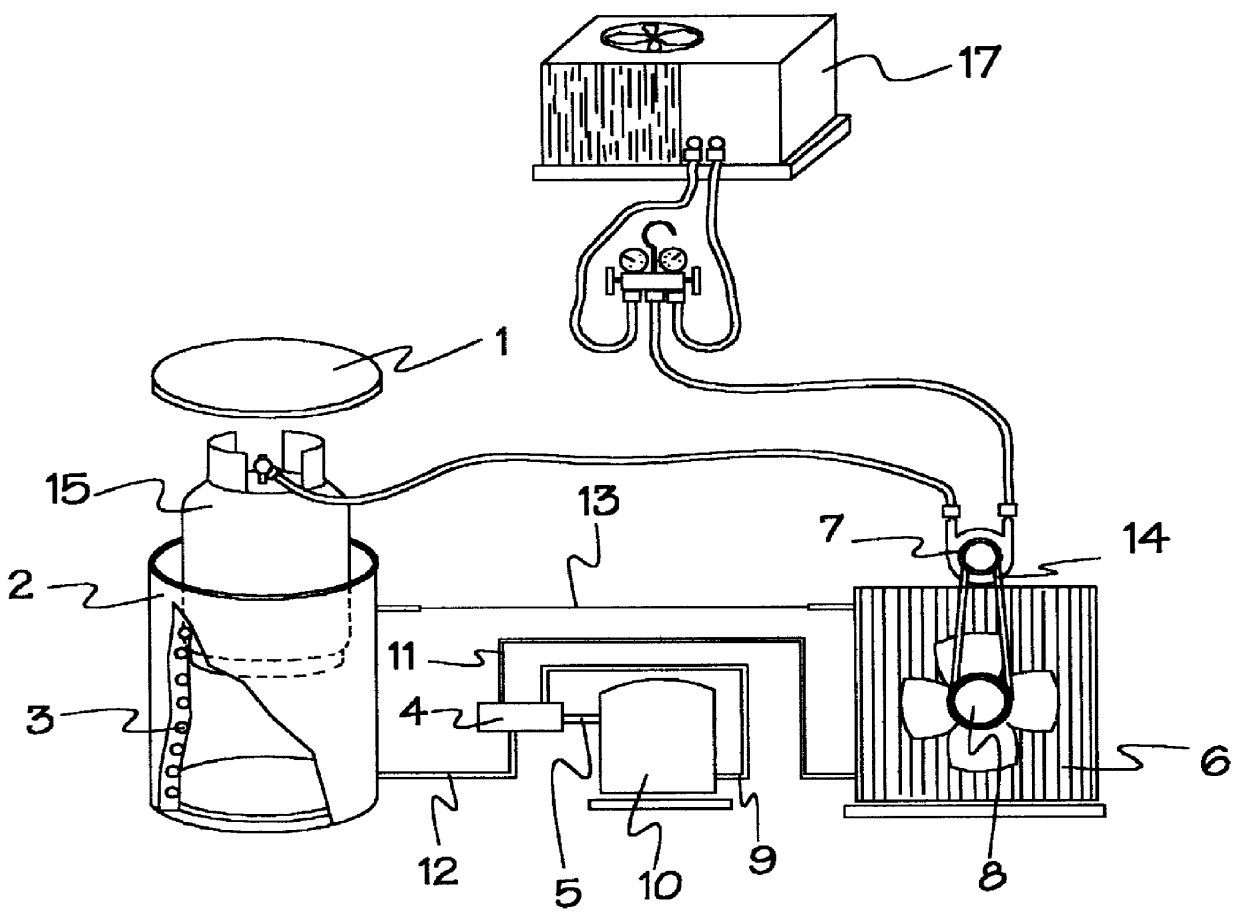
Referring to the drawing, FIG. 1 shows a perspective view of the present invention. The recovery pump 7 recovers refrigerant into a recovery tank. It withdraws refrigerants out from a system being recovered and discharges refrigerants in high pressure. The high-pressure refrigerant flows into the recovery tank, and the pressure inside the recovery tank simultaneously builds up. The recovery tank is kept in the refrigerated container 2, with lid 1, to hold down its pressure by lower its temperature. The cylinder wall of this container has a spiral refrigeration coil 3, which is working together with the other refrigeration components, including compressor 10, condenser coil 6, condenser fan 8 and the expansion metering device 13. The compressor 10 removes heat out from the coil 3 in container 2 to the condenser coil 6. The condenser coil 6 ejects heat by the condenser fan 8 blowing hot air out from the condenser coil 6.

The pump 7 may work in different fashions. Typically, the pump 7 ...


PUM


Abstract

The refrigeration recovery system equips with a refrigerated container to cool the recovery tanks in order to have a desirable low pressure inside the recovery tank. This method is essential to accelerate the recovery speed and to achieve a complete recovery of refrigerants.

Description

1. Field of the InventionThis invention relates to refrigerant recovery system, which is used for recovering gas and liquid refrigerants from air-conditioning and refrigeration systems, reclaiming used refrigerants into a recovery tank for recycling.2. Description of the Prior ArtThe HVACR industries had undergone a gigantic change since the phase out of ozone-depleting chlorofluorocarbon (CFC)-based refrigerants. In part of this U.S. clean air acts, we required to reclaim all refrigerants. Venting refrigerant into our air is no longer allowed. To comply with this earth shaking new law, a recovery system is needed for recovering refrigerants. Nevertheless, most technicians handling refrigerants are honestly complying with this new law. However, the sincere motivation to comply with the law is frequently failed due to the recovery systems often not doing it job well.The recovery systems currently available in the industry have two common problems, the recovering speed is too slow and...

Claims


Application Information

Patent Timeline
IPC IPC(8): F25B45/00F17C5/00F17C5/02F17C5/06F17C7/00F17C7/02
CPCF17C5/02F17C7/02F25B45/00F17C5/06F17C2223/033F25B2345/002F17C2205/0364F17C2221/038F17C2227/0337F17C2205/0323F17C2227/0135F17C2227/0157F17C2227/04F17C2201/0109F17C2205/0176F17C2205/0308
Inventor SZUTU, HUI JEN
Owner SZUTU HUI JEN
Why Eureka
Try Eureka