Hydraulic damper with elastomeric spring assembly

a technology of elastomeric springs and dampers, which is applied in the direction of shock absorbers, mechanical equipment, transportation and packaging, etc., can solve the problems of increasing costs, requiring product improvements to civil and military helicopters, and extending the damper full-length, so as to reduce the amount of force required to compress the piston. , the effect of reducing the amount of force required

Inactive Publication Date: 2001-01-02
MD HELICOPTERS INC
View PDF14 Cites 3 Cited by
  • Summary
  • Abstract
  • Description
  • Claims
  • Application Information

AI Technical Summary

Benefits of technology

Accordingly, it is an object of the invention to provide a damper assembly for aircraft landing gears that permit high nitrogen pressures to increase ground resonance clearance at high aircraft gross weight and not be fully extended at low aircraft gross weights to avoid ground resonance problems.
It is another object of the invention to provide a cost effective damper assembly that is easily retrofitted into current designs of helicopter landing gears.
In order to achieve this and other objects of the invention, a hydraulic damper assembly is provided having a barrel-piston assembly and a spring assembly. The barrel-piston assembly has a barrel with a top portion having an open end, and a piston extending through the open end. The piston has a bottom portion that is located inside the barrel. The piston and the barrel also define an annular space in which is a barrel shoulder and a piston shoulder. The barrel shoulder radially extends into the annular space from the barrel top portion. The piston shoulder radially extends into the annular space from the piston bottom portion. The spring assembly is disposed in the annular space between the barrel shoulder and the piston shoulder. When the piston is extended from the barrel, the shoulders compress the spring assembly and, thereby, reduce the amount of force required to compress the piston.

Problems solved by technology

However, higher nitrogen pressures result in full extension of the damper under low load conditions, which is not desirable.
This can be overcome by going to multistage shock struts with controlled mechanical failures, but at an increased cost.
A complication in changing damper design is that product improvements to both civil and military helicopters need to be accomplished with minimal changes to the existing landing gear configurations.
The existing shock strut designs are already at the limits of current technology and, therefore, cannot be scaled to accommodate the derivative helicopters with higher gross weights without an infusion of new and innovative technologies and design approaches.

Method used


Image

  • Hydraulic damper with elastomeric spring assembly
  • Hydraulic damper with elastomeric spring assembly
  • Hydraulic damper with elastomeric spring assembly

Examples


Embodiment Construction

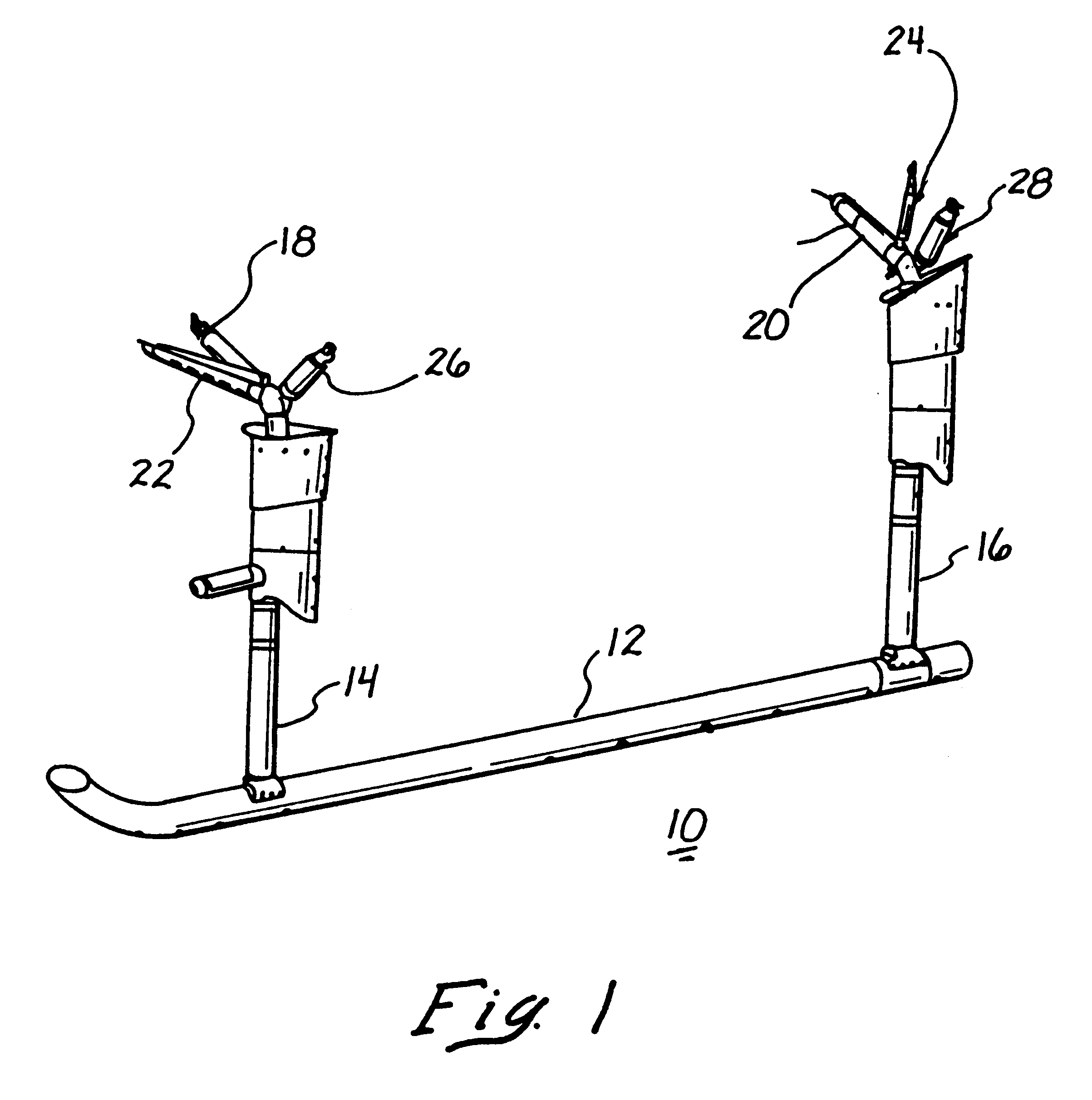
Referring now to the drawings, wherein like reference numerals designate corresponding structures throughout the views, and referring in particular to FIG. 1, a helicopter landing gear 10 according to an embodiment of the invention is shown. The landing gear 10 has a skid tube 12 from which radially extends a front foot 14 and a rear foot 16. The feet 14 and 16 extend to struts 18 and 20 respectively. From where the struts 18 and 20 join the feet 14 and 16, respectively, braces 22 and 24 and nitrogen-oil dampers 26 and 28 extend. The braces 22 and 24 and the dampers 26 and 28 are attached to the body of the helicopter (not shown). During landing of the helicopter, the dampers 26 and 28 absorb a portion of the landing forces.

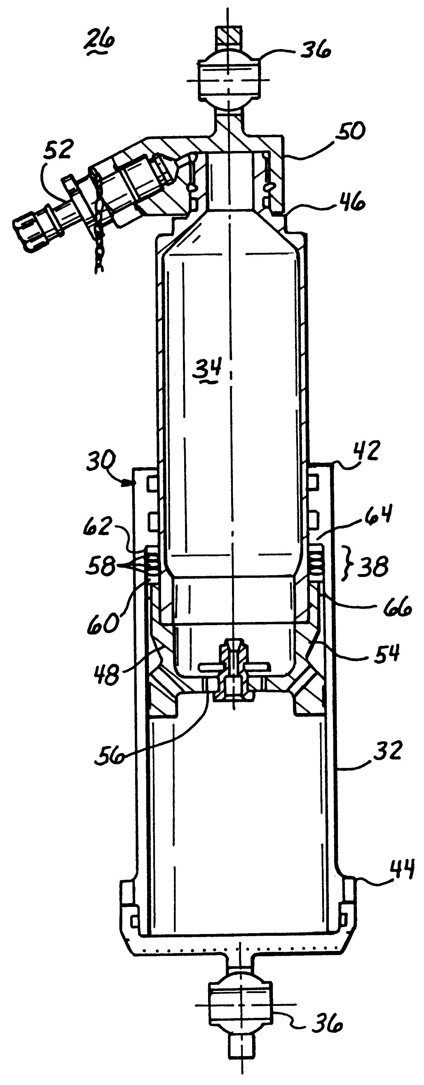
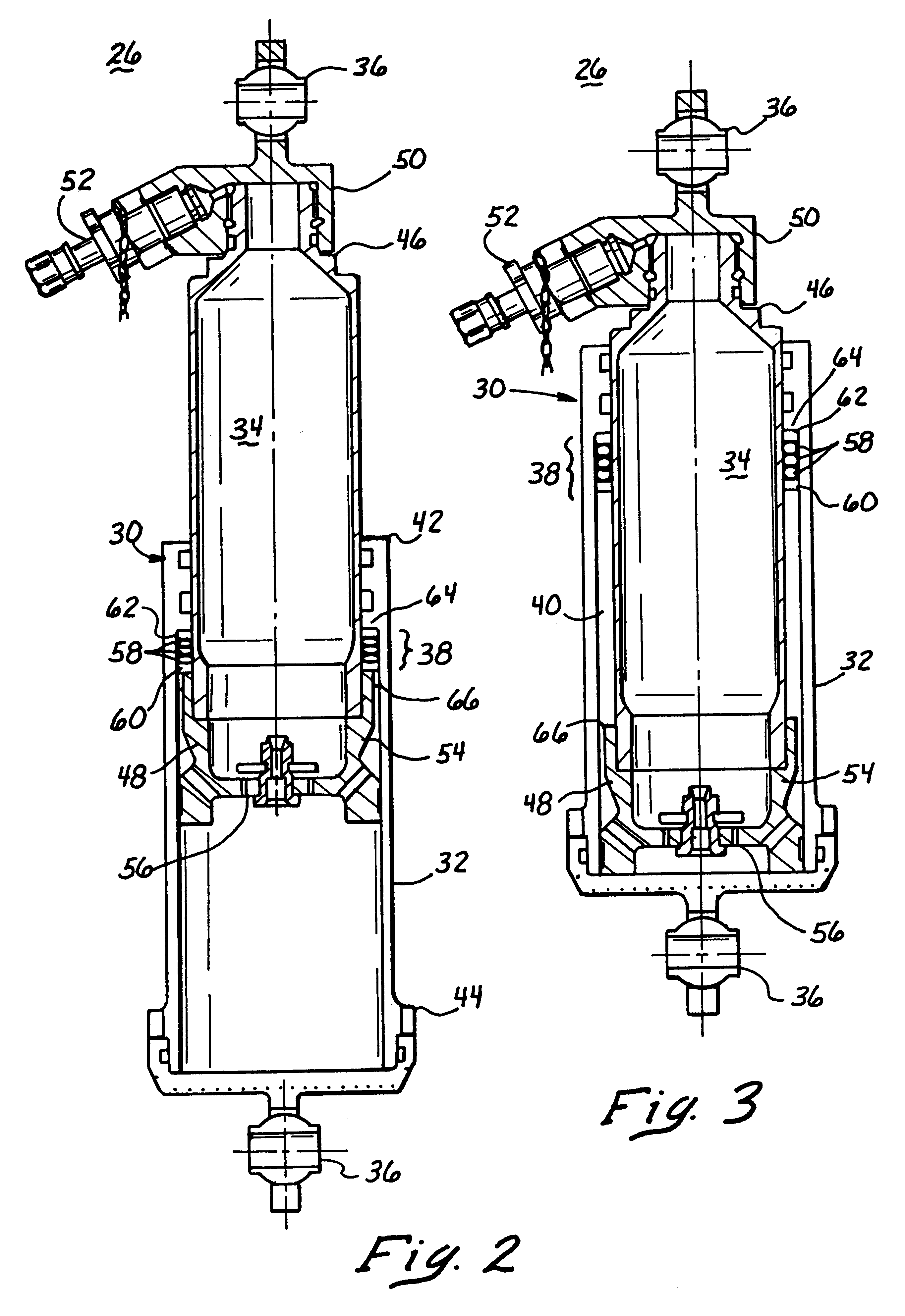
Now referring to FIGS. 2 and 3, details of the damper 26 according to the invention are shown. As with dampers known in the art, damper 26 has a barrel-piston assembly 30 with a barrel 32 and a piston 34 therein. FIG. 2 shows the damper 26 in the fully extended p...


PUM


Abstract

A hydraulic damper assembly has a barrel-piston assembly and a spring assembly. The barrel-piston assembly has a barrel with a top portion having an open end, and a piston extending through the open end. The piston has a bottom portion that is located inside the barrel. The piston and the barrel also define an annular space in which is a barrel shoulder and a piston shoulder. The barrel shoulder radially extends into the annular space from the barrel top portion. The piston shoulder radially extends into the annular space from the piston bottom portion. The spring assembly is disposed in the annular space between the barrel shoulder and the piston shoulder. When the piston is extended from the barrel, the shoulders compress the spring assembly and, thereby, reduce the amount of force required to compress the piston which enables the damper to be charged to a higher nitrogen pressure. An object of the invention is to provide a damper assembly for aircraft landing gears that permit high nitrogen pressures to increase ground resonance clearance at high aircraft gross weight and not be fully extended at low aircraft gross weights to avoid ground resonance problems. Another object of the invention is to provide a cost effective damper assembly that is easily retrofitted into current designs of helicopter landing gears.

Description

BACKGROUND OF THE INVENTION1. Field of the InventionThis invention relates to landing gear for aircraft, and particularly helicopters. More specifically, this invention relates to improvements in the hydraulic damper assembly that provide increased ground clearance of the helicopter under various conditions while maintaining appropriate ground resonance performance.2. Description of the Related ArtAircraft landing gears are typically equipped with hydraulic damper systems and struts to absorb forces during aircraft landing and to help support the aircraft while on the ground. Hydraulic damper systems are present in airplanes, helicopters, and other aircraft. Helicopter landing gears absorb the energy from landings through damper motion and elastic deformation of struts.Helicopter landing gears have unique design requirements. The military helicopter landing gears are required to function in vertical sink speeds ranging from 8 ft / sec limit landing to 42 ft / sec crash landing condition...

Claims


Application Information

Patent Timeline
Patent Type & Authority Patents(United States)
IPC IPC(8): F16F9/02F16F9/58
CPCF16F9/0218F16F9/585
Inventor BOLUKBASI, AKIF O.SALIBA, PAULPESTER, LOWELL
Owner MD HELICOPTERS INC
Why Eureka
Try Eureka