Super-abrasive grain-containing composite material and method of making

Inactive Publication Date: 2001-01-09
2 KANAGAWA
View PDF6 Cites 28 Cited by
  • Summary
  • Abstract
  • Description
  • Claims
  • Application Information

AI Technical Summary

Benefits of technology

The composite of the invention is effectively produced by:
(1) mixing a composition of powders so formulated as to be capable of undergoing an SHS process to yield a ceramic product and forming into one or more pellets, with superabrasive particles being distributed at least in the region to serve finally as the working surface; (2) arranging the pellet or pellets in the adjacency of said metallic block to complete the material syste

Problems solved by technology

However carbide alloy, being a hard and brittle material, cannot fully comply with the residual stresses which occur at the carbide and superabrasive interface after cooled down due to the difference in thermal expansion coefficient.
They may eventually cause to disjoint the laye

Method used


Image

  • Super-abrasive grain-containing composite material and method of making
  • Super-abrasive grain-containing composite material and method of making
  • Super-abrasive grain-containing composite material and method of making

Examples


example 1

A starting material was prepared from 1:1 mixed powder of 22 .mu.m (nominal size; effective and saved hereinafter unless otherwise indicated) titanium and 7 .mu.m carbon, by adding 25 wt % nickel powder (under 300 mesh). It is then formed in a die into a square pellet of 100.times.100.times.5 mm.

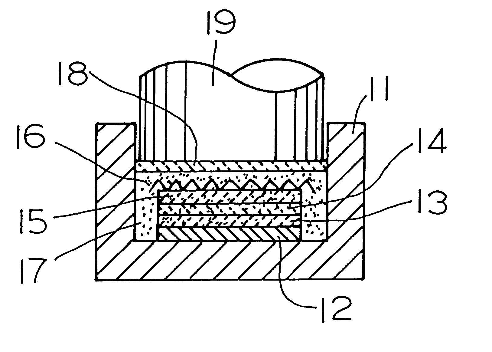
Another dose of mixed powder of starting material composition was admixed with 30% by volume of 20 / 30 .mu.m diamond powder and compressed into a second pellet of the same dimensions. The arrangement shown in FIG. 1 was used for further operation.

In the die 11 first placed a 100.times.100.times.3 mm wide SUS stainless steel plate 12, then the first formed pellet 13 and at the top the second pellet 14.

Over the assembly spread was 30 grams of 1:1 (in molecular ratio) mixed powder of Ti and C as an igniting medium 15 and a graphite heater 16. The space between said assembly and die 11 was filled with molding sand 17; a punch 19 was laid over it with an insulator sheet of ceramic 18. The graphite...

example 2

An excavator edge was tentatively prepared. Powders of 22 .mu.m Ti, 7 .mu.m carbon and under 325 mesh Al were dosed in a Ti:C:Al proportion by weight of 73:11:16 (16) and mixed well to prepare the matrix starting material. The latter was admixed with 1 wt % of TiH2 and further with 25 volume % of 40 / 60 .mu.m diamond particles, mixed fully and formed in a die at a pressure of 10 Mpa into truncated conical pellet which measured 40 mm across at the base and 10 mm thick, with a point angle of 120 degree.

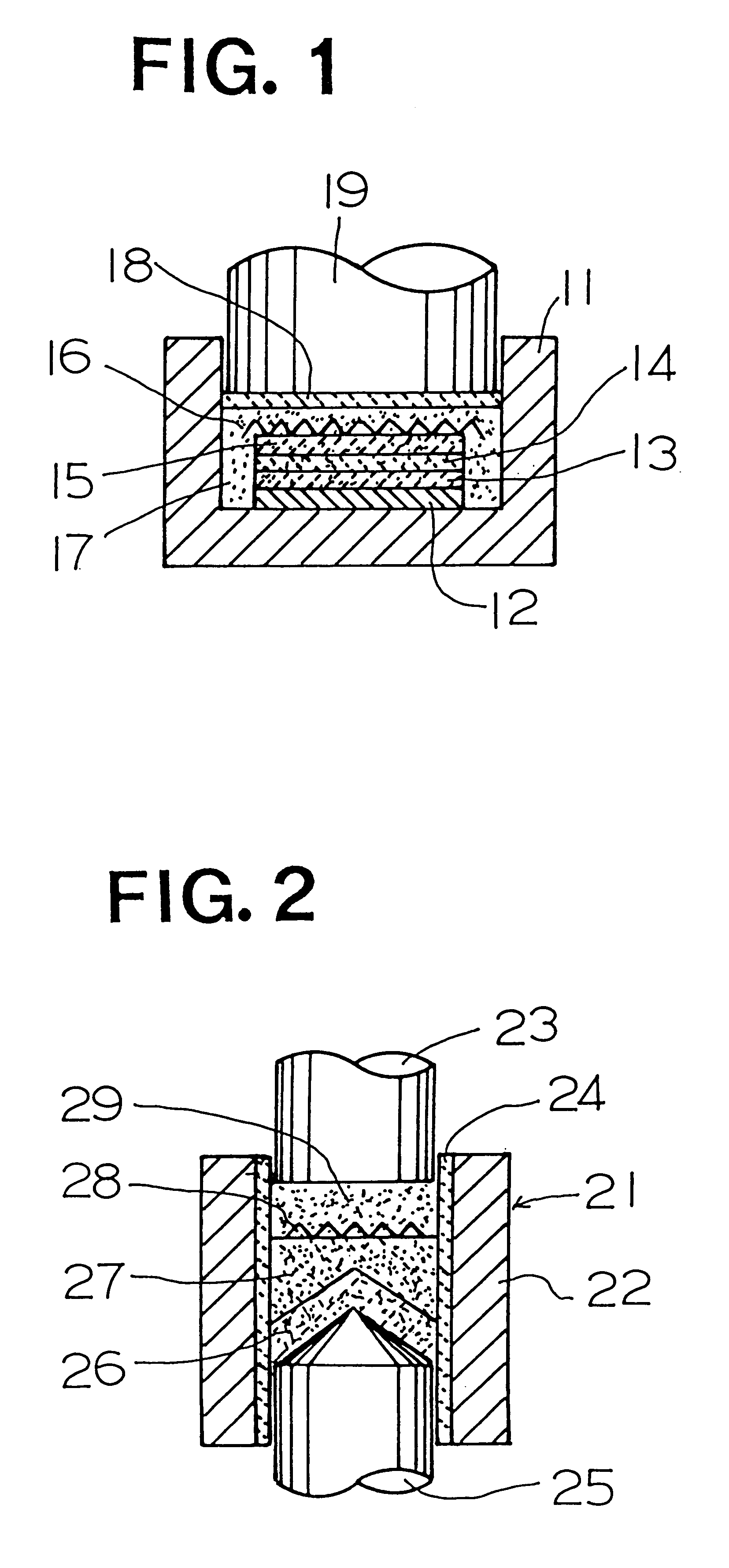
The arrangement shown in FIG. 2 was used, in which the die set 21 comprised a core 22 with a bore 40 mm across and 65 mm long, and a punch 23. A sleeve 24 of sintered mullite is fitted inside the core 22. A support member of SUS stainless steel 25, conically pointed at an angle of 120 degrees was set in the core 21 at the bottom, then the pellet 26 was placed over it. Over the pellet, 30 grams of 1:1 Ti--C mixed powder 27 was loaded and graded, then came an igniter of graphite ribbon 28,...

example 3

The functional layer material was composed of 80Ti / 20B mixed powder, which was further admixed with 33 vol. % of 12 / 25 .mu.m diamond particles. The die with a 75 mm across cylindrical cavity was loaded of a 10 mm thick SUS plate at the bottom, then a 0.5 mm thick Ni sheet, over which 40 grams of Ti--B mixed powder with diamond particles was spread and graded. Then came 25 grams of of 1:1 (in molecular ratio) Ti--C mixed powder as a chemical oven at the top.

Further a graphite igniter was placed; it was covered with a 10 mm thick layer of molding sand, on which the upper punch was arranged.

The process temperature was monitored by means of a thermocouple which was set in the through hole provided in the SUS plate at the center, while the heating and compression was conducted as in example 1.

The product was a wear resistant composite body of 2 mm thick TiB layer deposited on the SUS steel plate, and EPMA conducted on the product section showed a 1 mm wide gradient in Ni concentration fr...


PUM

PropertyMeasurementUnit
Timeaaaaaaaaaa
Timeaaaaaaaaaa
Thicknessaaaaaaaaaa

Abstract

The invention provides a superabrasive containing composite product, comprising and/or prepared on the intense heating of an SHS process, self-propagating high-temperature synthesis. An effective method of such product is also provided. Said composite comprises a substrate of shaped metallic block and a functional layer of ceramic materials containing superabrasive particles, which is joined on a surface of the former, by means of and intermediated by molten metal which occurred during the SHS process.

Description

This invention relates to a composite comprising wear-resistant material with superabrasive particles and ductile metal. Common structural metallic materials can be used to make the substrate, which may be a block in various forms (including plates), and they are prepared either through a compressive work such as forging, rolling, extrusion and HIPping or by foundry.BACKGROUND TECHNIQUEAs wear-resistant materials comprising superabrasive particles, diamond or cubic boron nitride compacts are commercially produced mainly in ultrahigh pressure processes, and in which the superabrasive particles are joined immediately with each other or distributed in a ceramic matrix. While the compacts may be employed as a block of totally uniform structure, they are more commonly used as a composite with a carbide backing to which the superabrasive particles are joined during the sintering of the particles themselves. The latter composition is taken mainly as demanded in the subsequent steps of mach...

Claims


Application Information

Patent Timeline
IPC IPC(8): B22F3/00B22F7/08B22F3/23B22F7/06C04B37/02C22C1/05B22F7/04
CPCB22F3/23B22F7/062C22C1/058B22F7/08Y10T428/12007B22F2005/001B22F7/04C04B37/02
Inventor KOIZUMI, MITSUEOHYANAGI, MANSHIHOSOMI, SATORULEVASHOV, EVGENY A.TROTSUE, ALEXANDER V.BOROVINSKAYA, INNA P.
Owner 2 KANAGAWA
Why Eureka
Try Eureka