Freestanding multilayer wiring structure

a freestanding, multi-layer technology, applied in the direction of basic electric elements, cable/conductor manufacturing, solid-state devices, etc., can solve the problems of increasing the length of unsupported wire, reducing the approach, and not eliminating the shorting of air dielectric ic structur

Inactive Publication Date: 2001-01-09
GLOBALFOUNDRIES INC
View PDF12 Cites 28 Cited by
  • Summary
  • Abstract
  • Description
  • Claims
  • Application Information

AI Technical Summary

Problems solved by technology

Although scanning electron microscopic (SEM) images of such structures clearly show that small lengths of wire are self supporting, longer lengths of wire are not self-supporting.
So, longer lengths of unsupported wire are susceptible to shorting.
This approach reduces, but does not eliminate shorting in an air dielectric IC structure.
The above examples of the prior art incur a substantial wiring density penalty because the support pillars extend through several wiring levels, all the way up from an underlying substrate.
However, any dielectric must be removed after the planar layer is formed by complex venting and filling steps or the dielectric is trapped under the permanent planar layer.
Unfortunately, Aitken stud opening diameters must be significantly wider (twice the thickness of the dielectric tube) than the studs themselves, which must be significantly larger than the minimum process dimension.
Further, circuit design is more complicated because the wiring and the support pedestals must be accounted for on each wiring level.
Materials used in prior art methods are exotic and, so, are expensive to develop and difficult to remove.
Parylene has a low decomposition temperature, which severely restricts the materials that can be used for the freestanding structures.
Furthermore, typical prior art methods use aqueous chemicals to etch the removable material.
It is uncertain whether these aqueous chemicals can penetrate the convoluted paths to regions buried deep within the wiring that must be cleared of removable dielectric.
In particular, when dielectric removal is deferred until the end, or, for structures with vented planar layers such as U.S. Pat. No. 5,324,683 to Fitch et al. entitled "Method of Forming a Semiconductor Structure having an Air Region" (which is even more complex than Kaanta), these aqueous chemicals penetrate vent holes with considerable difficulty.
Further, after reaction and drying, the reaction products may not be removed completely from the nearly enclosed air dielectric compartments.
These small openings make it difficult for reactants to diffuse in, or for waste products to diffuse out, when the cavities are filled with a liquid.
Additional problems arise when aqueous HF is used to remove oxides from the exposed metal lines.
Electrochemical potentials further contribute to corrosion of one metal of the composite.
Such an attack can result in open electrical circuits, higher line resistivity, and the metal lines separating from their supports.
Because sidewalls are formed after wiring, with the wiring at each level providing support definition, complex support alignment is unnecessary.

Method used


Image

  • Freestanding multilayer wiring structure
  • Freestanding multilayer wiring structure
  • Freestanding multilayer wiring structure

Examples


Embodiment Construction

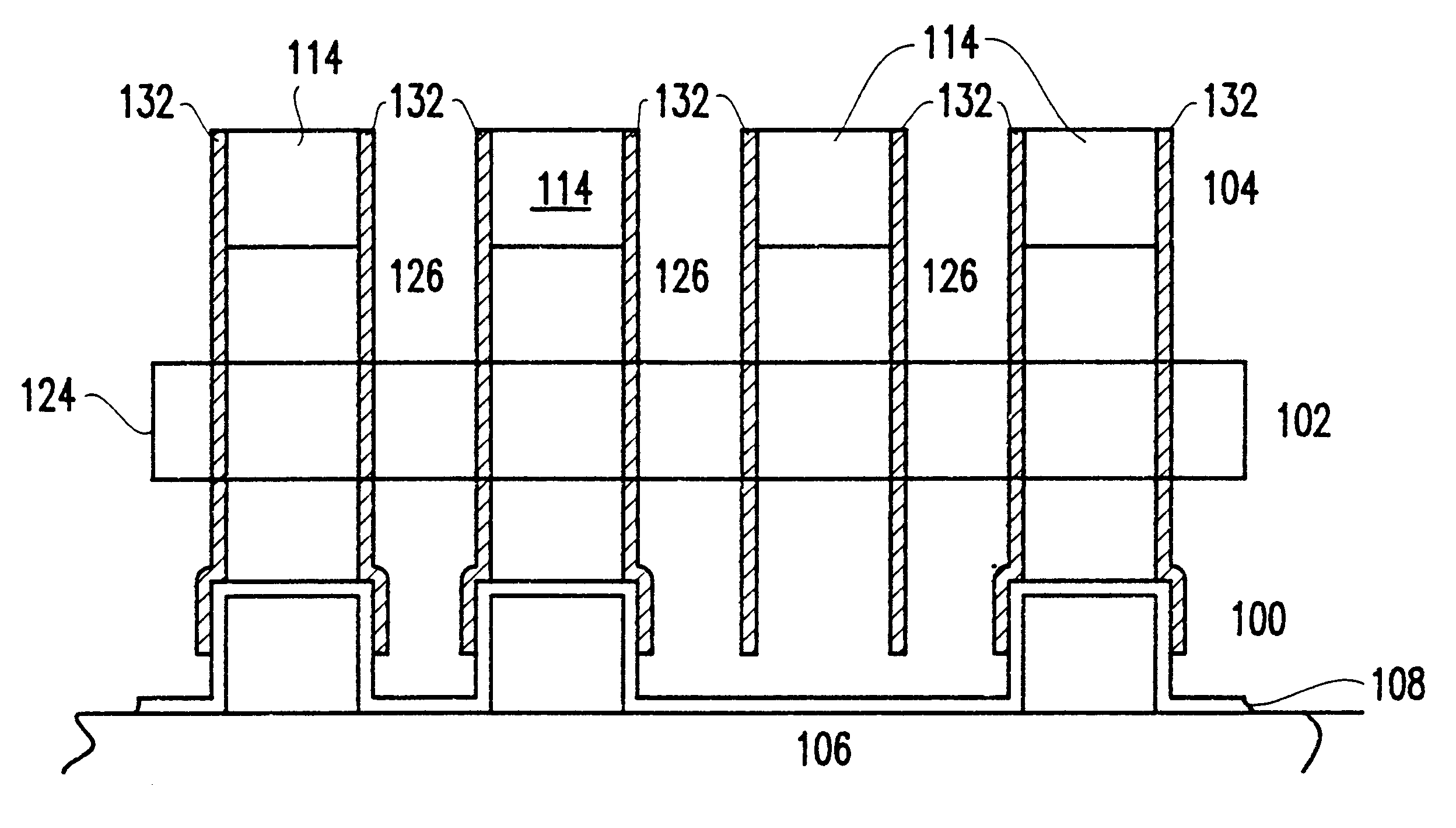
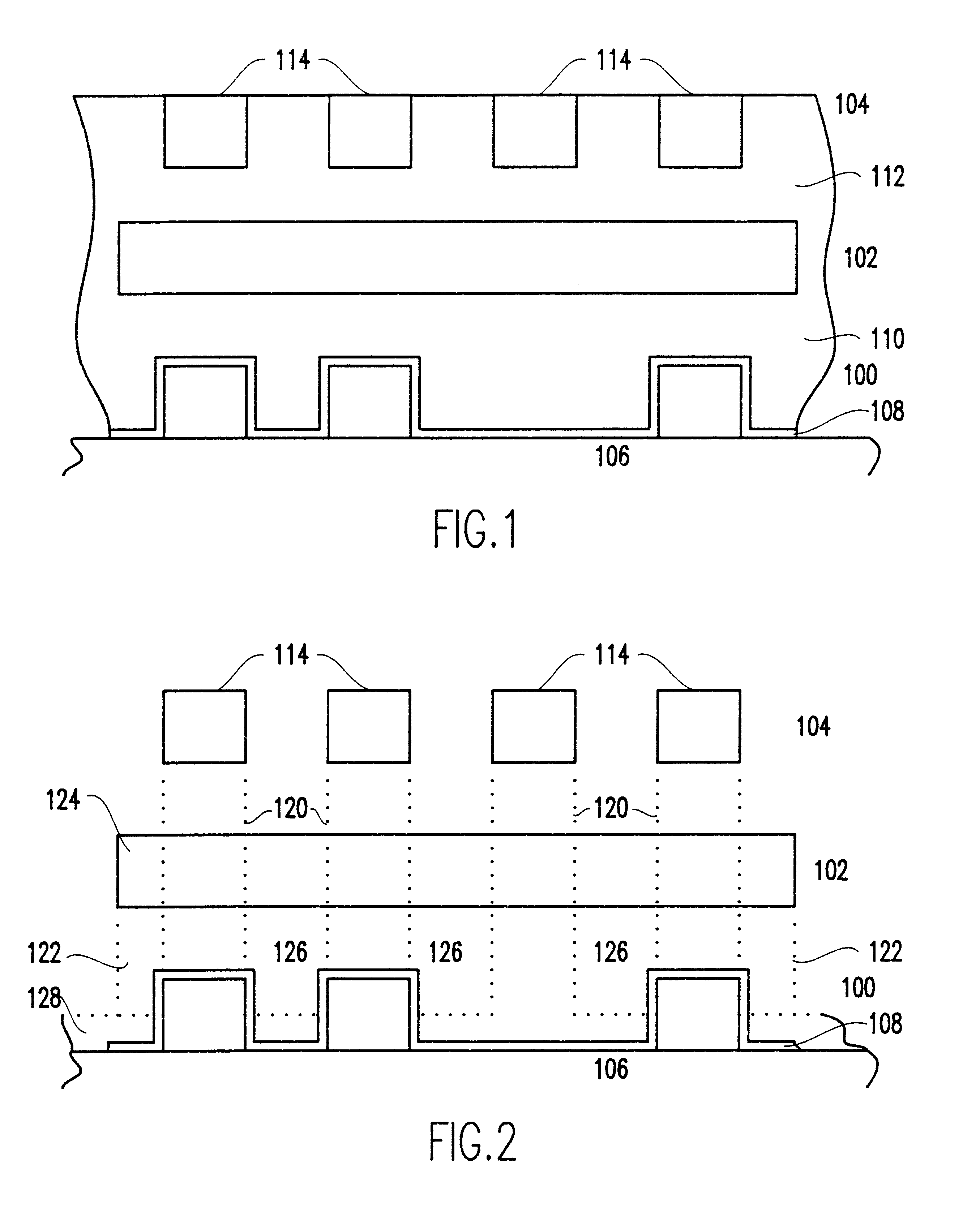
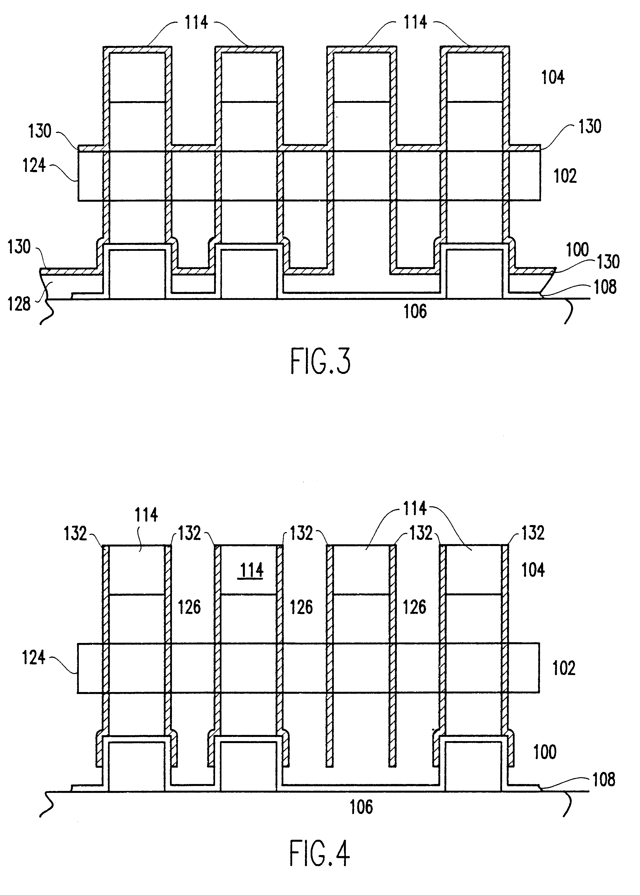
The inventor of the present invention discovered that gaseous HF may be used to remove silicon dioxide (SiO.sub.2) from a layered wiring structure without the normal damage to the wires. The damage that occurred in prior art methods was the result of using an aqueous solution to remove fill dielectric. The prior art aqueous solution invariably attacked the metal wires as it removed the fill dielectric. Although gaseous HF has been used to remove thin reactive ion etch (RIE) residues from metal lines, it was heretofore believed that the long exposures necessary for oxide dielectric removal were similarly corrosive.

However, as the inventor has found, using gaseous HF, preferably at a partial pressure between 5 and 30 Torr., SiO.sub.2 may be stripped completely away from a wiring structure, leaving the metal wires and studs behind unharmed. The gaseous reaction operates through formation of a thin aqueous film.

As a result of that discovery, the inventor further discovered that, in the ...


PUM

PropertyMeasurementUnit
partial pressureaaaaaaaaaa

Abstract

A dielectric wiring structure and method of manufacture therefor. Successively formed wiring layers synergistically combine with subsequently formed sidewall supports spanning two or more layers to form a self supporting air dielectric interconnection matrix. Wires are supported by vertical nitride sidewalls which are, in turn, held in place and supported by the wires. After forming the complete wiring-sidewall structure, SiO2 between and under the wires is removed using gaseous HF at a partial pressure between 5 and 30 Torr. The metal wires may be clad with nitride for short and oxidation protection. Because sidewalls are formed after wiring, with the wiring at each level providing support definition, complex support alignment is unnecessary.

Description

1. Field of the InventionThe present invention is related to Integrated Circuits (ICs) and, more particularly, to ICs having air dielectric wiring for reduced capacitance.2. Background DescriptionIntegrated circuit (IC) performance is dependent upon individual circuit performance. Individual circuit performance is dependent on the load the circuit must drive. For field effect transistor (FET) circuits, the primary load is capacitive. The primary source of the circuit load capacitance is inter-circuit wiring capacitance. Thus, IC performance can improved by reducing wiring capacitance.Typical IC chips with a large number of logic circuits include multiple layers of wires, called wiring layers, stacked one on top of another and separated by dielectric material. The ideal dielectric is air or, at least has the same dielectric constant as air. There are several approaches to providing an air dielectric in IC chips.Freestanding StructuresOne approach is to remove the dielectric around th...

Claims


Application Information

Patent Timeline
Patent Type & Authority Patents(United States)
IPC IPC(8): H01L23/522H01L23/52H01L21/768
CPCH01L21/7682H01L23/5222H01L2924/0002H01L2924/00
Inventor NATZLE, WESLEY CHARLES
Owner GLOBALFOUNDRIES INC
Why Eureka
Try Eureka