System for compensating polarization dispersion of channels in a wavelength-division multiplex signal
Inactive Publication Date: 2001-01-23
ALCATEL LUCENT SAS
View PDF6 Cites 8 Cited by
Summary
Abstract
Description
Claims
Application Information
AI Technical Summary
This helps you quickly interpret patents by identifying the three key elements:
Problems solved by technology
Method used
Benefits of technology
Benefits of technology
means for measuring the intensity of a component of that portion in a fixed polarization
Problems solved by technology
Deformation of the pulses received by the receiving terminal can cause errors in decoding the transmitted data and polarization dispersion is therefore a factor limiting the performance of optical links, whether analog or digital.
However, a high proportion of monomode fibers installed in the last decade have very high polarization dispersion, which constitutes a major technical obstacle to propagation of the transmitted bit rates.
Furthermore, if the bit rate race continues, there is nothing to prevent this problem appearing in the low polarization dispersion fibers that we now know how to produce.
Polarization dispersion is a difficult problem to solve in the context of upgrading existing optical fiber networks with channels having bit rates of 10 Gbit / s and above.
However, there is no means of solving the problem of polarization dispersion in a wavelength-division multiplex network other than juxtaposing identical single-channel compensator systems after demultiplexing.
Method used
Image
Click on the blue label to locate the original text in one second.
Reading with bidirectional positioning of images and text.
Examples
second embodiment
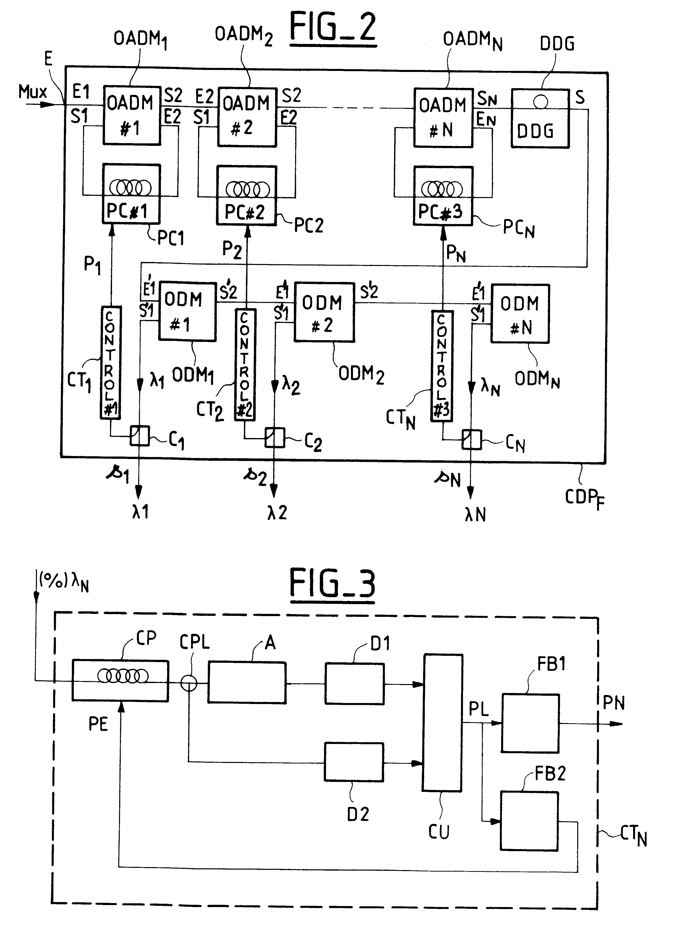
In a second embodiment, represented by the dashed lines in FIG. 4, the output of the polarization compensator CDP.sub.I is taken from the output of the last demultiplexer, in other words the output of demultiplexer ODM.sub.N, rather than the output of the differential delay generator DDG. For this, it is no longer necessary to place the coupler CS at the output of the generator DDG because all of the multiplex signal would be treated in the control loop. On the other hand, each demultiplexer would deliver at its output S'1 only a fraction of the extracted channel signal, the multiplexed optical signals of all the channels being supplied at the output S'2.
The compensated multiplex signal transmitted over the line is then available at the output S'2 of the last demultiplexer ODM.sub.N.
Embodiments of the various optimal demultiplexers ODM.sub.N that can be used to implement the polarization compensator of the invention, whether in-line or at the end of the line, will now be described i...
first embodiment
A first embodiment is shown in FIG. 5A in which the demultiplexer structure comprises a fiber segment with in-fiber Bragg gratings IFPG and a circulator C1 at the input of the fiber segment.
FIG. 5B shows a second embodiment. This embodiment is a Mach-Zehnder interferometer structure MZ with a fiber segment with in-fiber Bragg gratings IFBG in each branch of the interferometer structure. In practice the fiber of a branch is ultraviolet (UV) treated to match the phase difference between the two arms of the interferometer.
third embodiment
FIG. 5C shows a This is a coupler structure with respective couplers CPL1 and CPL2 and fiber segments with in-fiber Bragg gratings IFBG.
The fiber segments with in-fiber Bragg gratings can be fiber segments in which the Bragg grating is etched or photo-written, for example.
Three embodiments of the optical drop and insert multiplexers OADM.sub.N will now be described by way of example.
FIG. 6A shows a first embodiment which is a structure comprising a fiber segment with in-fiber Bragg gratings IFBG and a circulator C1-C2 at each end of the fiber segment.
FIG. 6B shows a second embodiment which is a Mach-Zehnder interferometer structure MZ with fiber segments and in-fiber Bragg gratings IFBG in each branch.
Finally, FIG. 6C shows a third embodiment in which the drop and insertmultiplexer has a coupler structure with fiber segments with couplers CPL1 and CPL2 and in-fiber Bragg gratings IFBG.
As mentioned with reference to FIGS. 5A to 5C, the fiber segments with in-fiber Bragg gratings ca...
PUM
Abstract
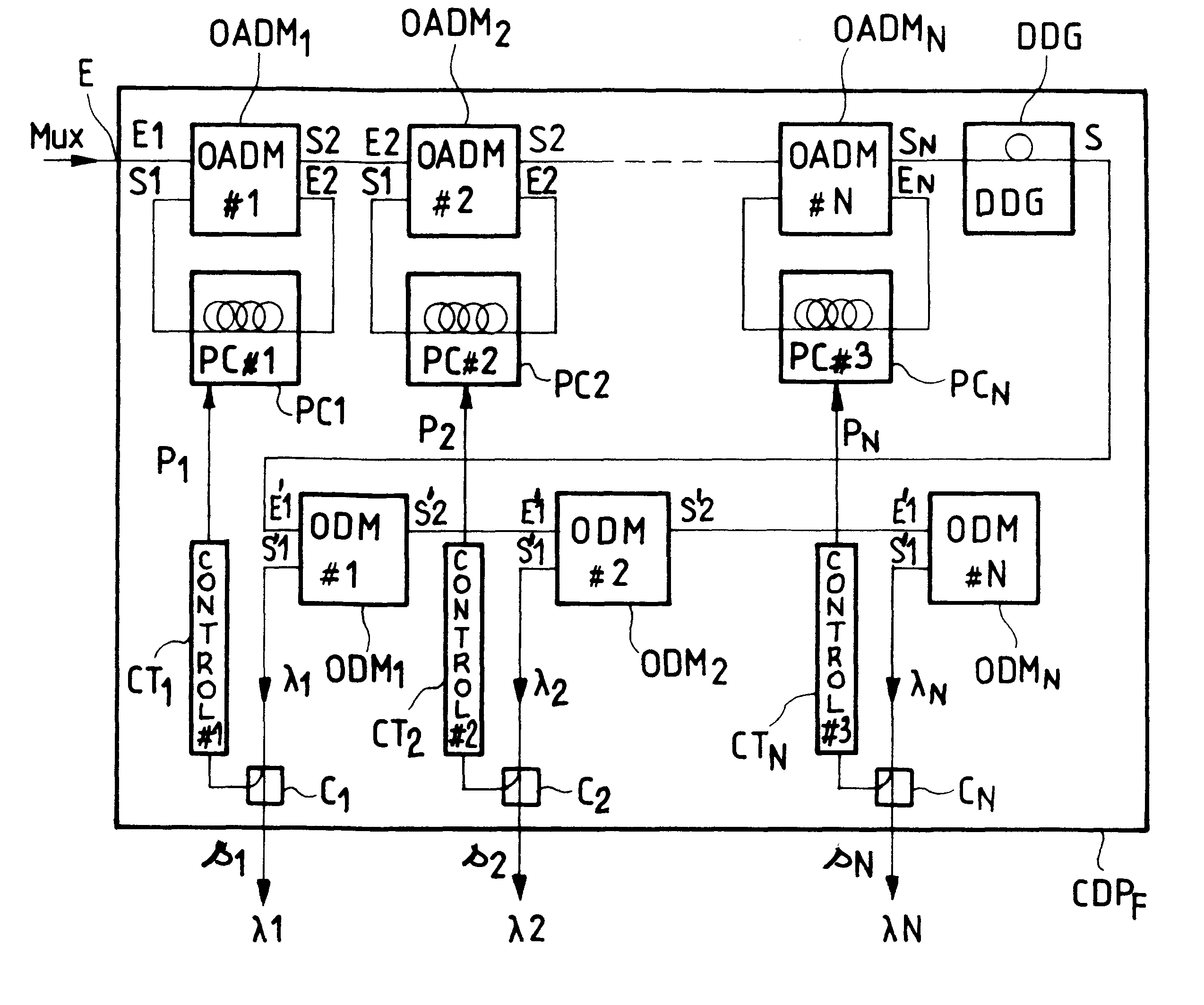
The invention concerns a system for compensating polarization dispersion of channels in a wavelength-division multiplexsignal. In accordance with the invention, the system comprises a plurality of cascaded polarization control modules respectively associated with said channels and a common differential delay generator.Each polarization control module comprises a drop and insertmultiplexer for extracting the signal from the associated channel from the input multiplexsignal and inserting a modified channel supplied by a polarization controller.The system further comprises a control loop for controlling the polarization controllers in response to the optical properties of the channel signals at the output of the differential delay generator and obtaining a compensated multiplex signal.
Description
The invention concerns a device for compensating polarization dispersion of channels in a wavelength-division multiplex signal.The invention applies to wavelength-division multiplex (WDM) transmission systems.All types of fiber are subject to polarization dispersion: a pulse sent by a sending terminal is deformed when it is received. Its duration is greater than its original duration. The deformation is due to the fact that the optical signal is depolarized during transmission. The signal received at the end of the connecting fiber may be considered to comprise two orthogonal components, one corresponding to a maximum propagation speed polarization state (fastest main polarization state) and the other corresponding to a minimum propagation speed polarization state (slowest main polarization state).In other words, a pulse signal received at the end of the connecting fiber may be considered to comprise a first pulse signal polarized in accordance with an advanced polarization state an...
Claims
Application Information
Patent Timeline
Application Date:The date an application was filed.
Publication Date:The date a patent or application was officially published.
First Publication Date:The earliest publication date of a patent with the same application number.
Issue Date:Publication date of the patent grant document.
PCT Entry Date:The Entry date of PCT National Phase.
Estimated Expiry Date:The statutory expiry date of a patent right according to the Patent Law, and it is the longest term of protection that the patent right can achieve without the termination of the patent right due to other reasons(Term extension factor has been taken into account ).
Invalid Date:Actual expiry date is based on effective date or publication date of legal transaction data of invalid patent.

