Overburden drilling apparatus having a down-the-hole hammer separatable from an outer casing/drill bit unit

a technology of overburden drilling and drill bit, which is applied in the direction of drilling pipes, drilling holes/well accessories, cutting machines, etc., can solve the problems of ring bit wearout, inability to use the known device, and bit wearou

Inactive Publication Date: 2001-02-06
SANDVIK INTELLECTUAL PROPERTY AB
View PDF14 Cites 112 Cited by
  • Summary
  • Abstract
  • Description
  • Claims
  • Application Information

AI Technical Summary

Benefits of technology

Specifically one object of the present invention is to provide efficient drilling equipment able to drill deeply into rock while casing the hole.
Another object of the present invention is to provide a drill bit for a down-the-hole hammer which provides for long drilling lengths.
Still another object of the present invention is to provide efficient drilling equipment, wherein the hammer is releaseably connected to a non-retractable one-piece road embankment drill bit.
One aspect of the present invention relates to an overburden drilling equipment for drilling a hole. The equipment comprises a cylindrical casing defining a longitudinal axis and having a diametrically reduced structure forming at least one longitudinally extending keyway. A drill bit is disposed in the casing and includes a cutting face located at a longitudinal front end thereof, and an anvil portion located at a longitudinal rear portion thereof. A generally cylindrical casing shoe is attached to the casing and mounted to the drill bit for lo

Problems solved by technology

Often, it is desirable for the casing to be left in the hole, but that is not possible with the known device.
However, in dee

Method used


Image

  • Overburden drilling apparatus having a down-the-hole hammer separatable from an outer casing/drill bit unit
  • Overburden drilling apparatus having a down-the-hole hammer separatable from an outer casing/drill bit unit
  • Overburden drilling apparatus having a down-the-hole hammer separatable from an outer casing/drill bit unit

Examples


Embodiment Construction

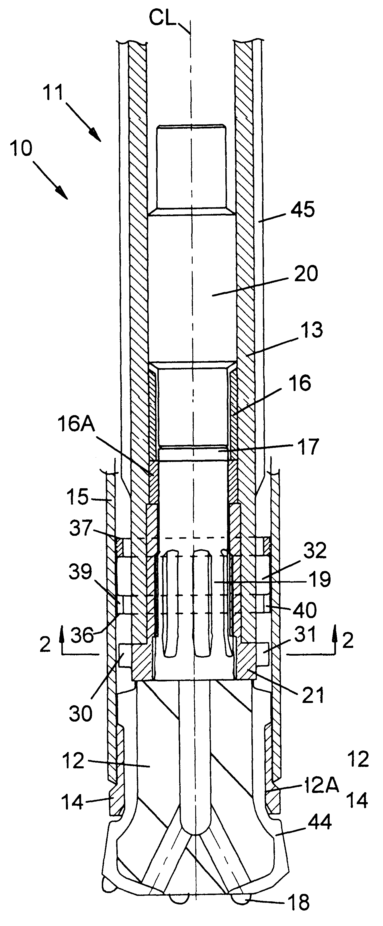
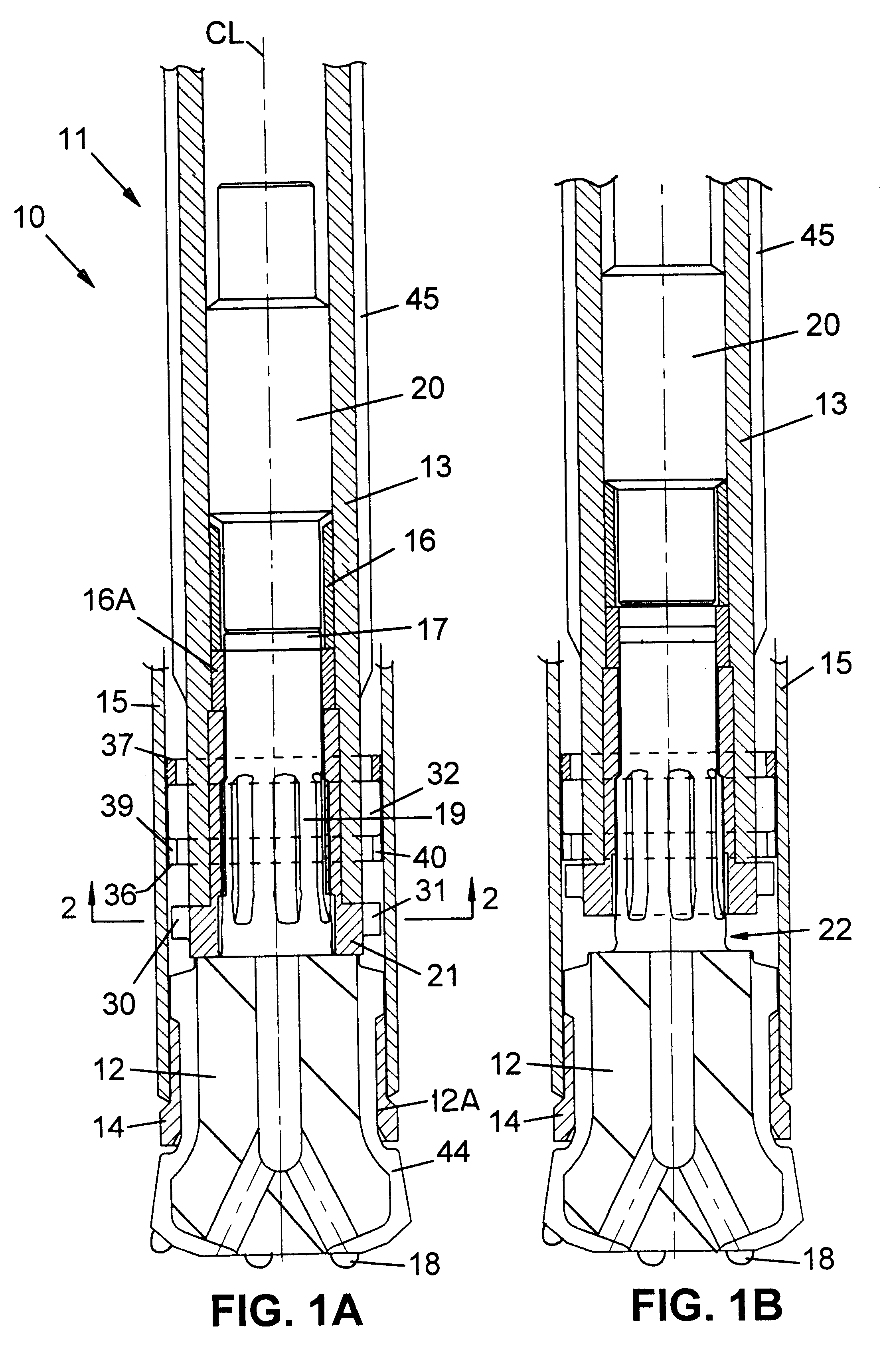
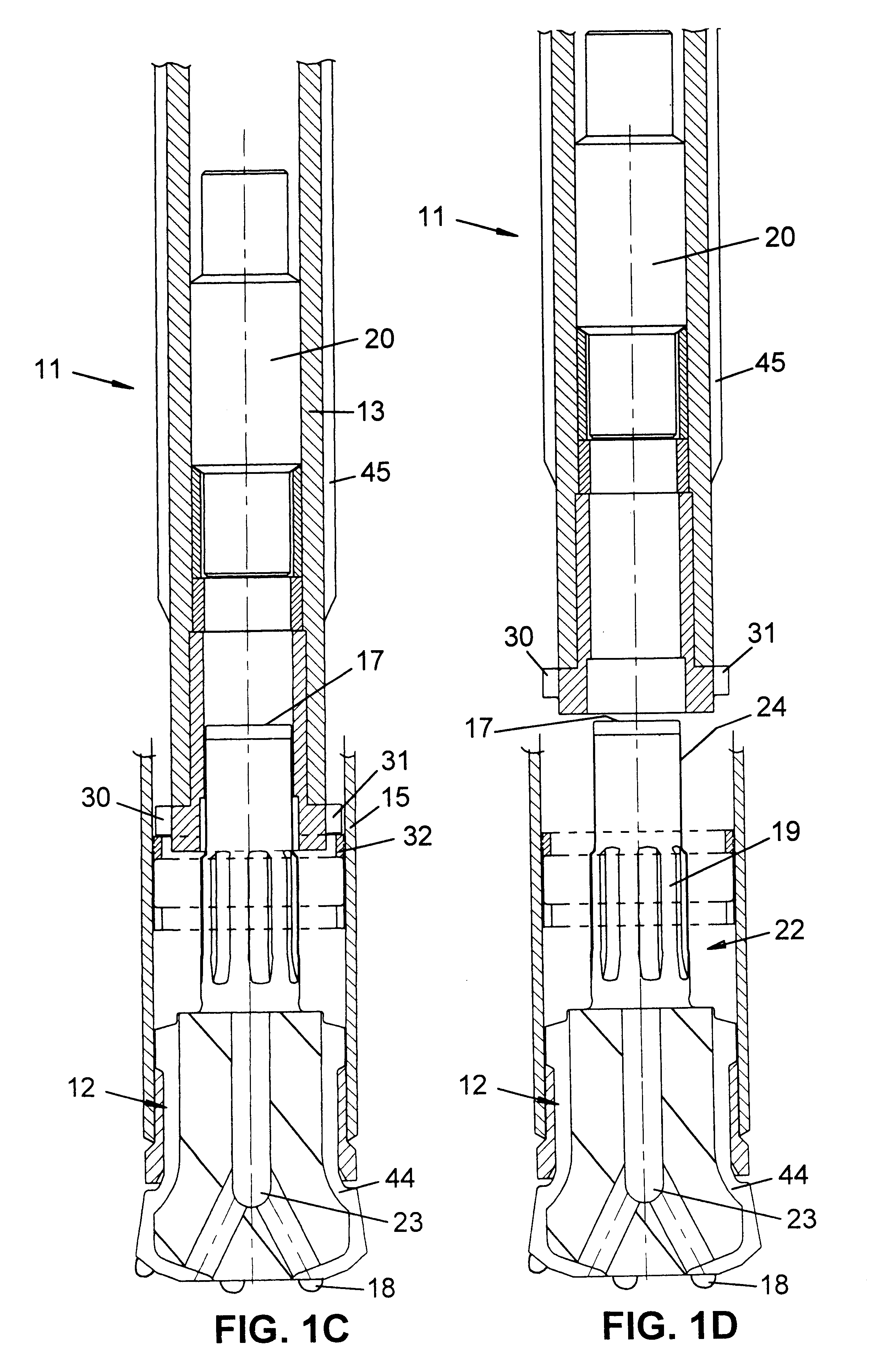
In FIGS. 1A-1D there is shown a preferred embodiment of overburden drilling equipment according to the present invention. The equipment 10 comprises a down-the-hole hammer 11, a drill bit 12, a casing shoe 14 and a casing 15.

The hammer 11 is a hydraulic, preferably water-driven, hammer as disclosed in U.S. Pat. No. 5,107,944 issued Apr. 28, 1992, the disclosure of which is incorporated by reference herein. The water-driven hammer drives a percussive drill bit 12. The down-the-hole hammer 11 is connected to a drill string, not shown. The drill string comprises a number of double leads, high pressure drill tubes duly sealed in the thread areas. A water-driven hammer will not affect the surrounding soil as much as air-driven tools with respect to erosion, oil pollution and noise. For example, with respect to erosion, the speed of water required to drive a water-driven hammer is about 1 m / s as compared to an air-driven hammer wherein the air speed is about 20 m / s. Furthermore, in a wate...


PUM


Abstract

Overburden drilling equipment for drilling a hole includes a down-the-hole hammer formed by a cylinder and a piston reciprocating in the cylinder due to pressurized water being directed alternately to the upper and lower ends of the piston. Each downward stroke inflicts an impact blow upon an anvil portion of a drill bit extending upwardly within the lower portion of the cylinder. A drill chuck is mounted at a lower end of the cylinder to receive the drill bit. A generally cylindrical casing shoe is attached to a casing and is rotatably connected to the drill bit to be longitudinally advanced thereby during drilling operation. The drill chuck includes at least one key which defines the largest radius of the drill chuck. The casing includes a diametrically reduced portion which has at least one keyway therein. The key and the diametrically reduced portion retain the hammer longitudinally in relation to the drill bit.

Description

TECHNICAL BACKGROUNDThe present invention relates to a drilling equipment, a driver sub and a drill bit for overburden drilling operations.PRIOR ARTOverburden drilling equipment is previously disclosed, for example, in llomaki U.S. Pat. No. 5,255,960 issued Oct. 26, 1993. It has been found favorable to construct overburden drilling equipment such that the casing and the rock drill bit are relatively rotatable while simultaneously axially connected, so that the drill bit pulls the casing along as the drill bit advances in the ground. The solution to such relative rotation is described in the abovenamed patent as a "lap-joint", wherein the casing, or a casing shoe attached to the front of the casing, axially overlaps the drill bit. A split collar welded to the inside of the casing projects into a circumferential groove formed in the drill bit, enabling the drill bit to pull the casing along. Often, it is desirable for the casing to be left in the hole, but that is not possible with th...

Claims


Application Information

Patent Timeline
IPC IPC(8): E21B17/07E21B17/02E21B7/20E21B4/14E21B4/00
CPCE21B4/14E21B7/208E21B17/076
Inventor ANG.SBERG, BENGT
Owner SANDVIK INTELLECTUAL PROPERTY AB
Why Eureka
Try Eureka