Scanning laser ophthalmoscope for selective therapeutic laser

a laser ophthalmoscope and laser technology, applied in the field of ophthalmoscopes, can solve the problems of novel approach, limited fashion, difficult delivery,

Inactive Publication Date: 2001-02-13
VAN DE VELDE JOZEK F
View PDF2 Cites 159 Cited by
  • Summary
  • Abstract
  • Description
  • Claims
  • Application Information

AI Technical Summary

Problems solved by technology

The confocal instrument can do this, however in a limited fashion.
However they usually rotate as well, making them useless when their anterior surface is not symmetric around the visual axis.
Nevertheless, this is still easy to deliver with a diode laser of 300 mW power output and a larger N.A. fiber optic delivery system.
This novel approach however is not ideal because of the difficulties in implementing safety controls for such a scanning therapeutic laser beam, the difficulty in modulating the scanning laser beam over a range from non-coagulating to coagulating energies at video bandwidth, and the non-thermal complications of a high intensity pulsed laser beam in the nanosecond domain combined with an inappropriate duty cycle.

Method used


Image

  • Scanning laser ophthalmoscope for selective therapeutic laser
  • Scanning laser ophthalmoscope for selective therapeutic laser
  • Scanning laser ophthalmoscope for selective therapeutic laser

Examples


Embodiment Construction

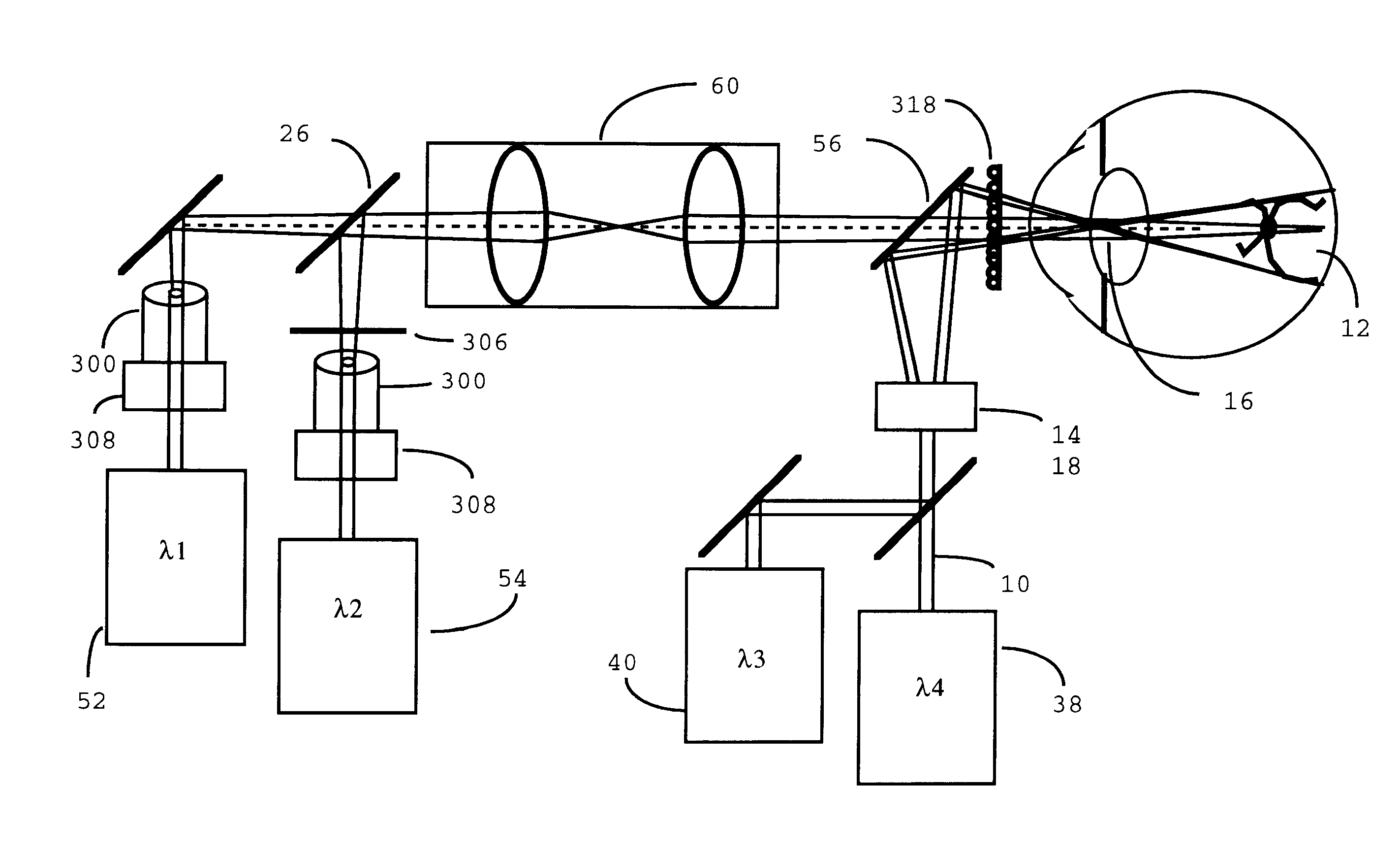
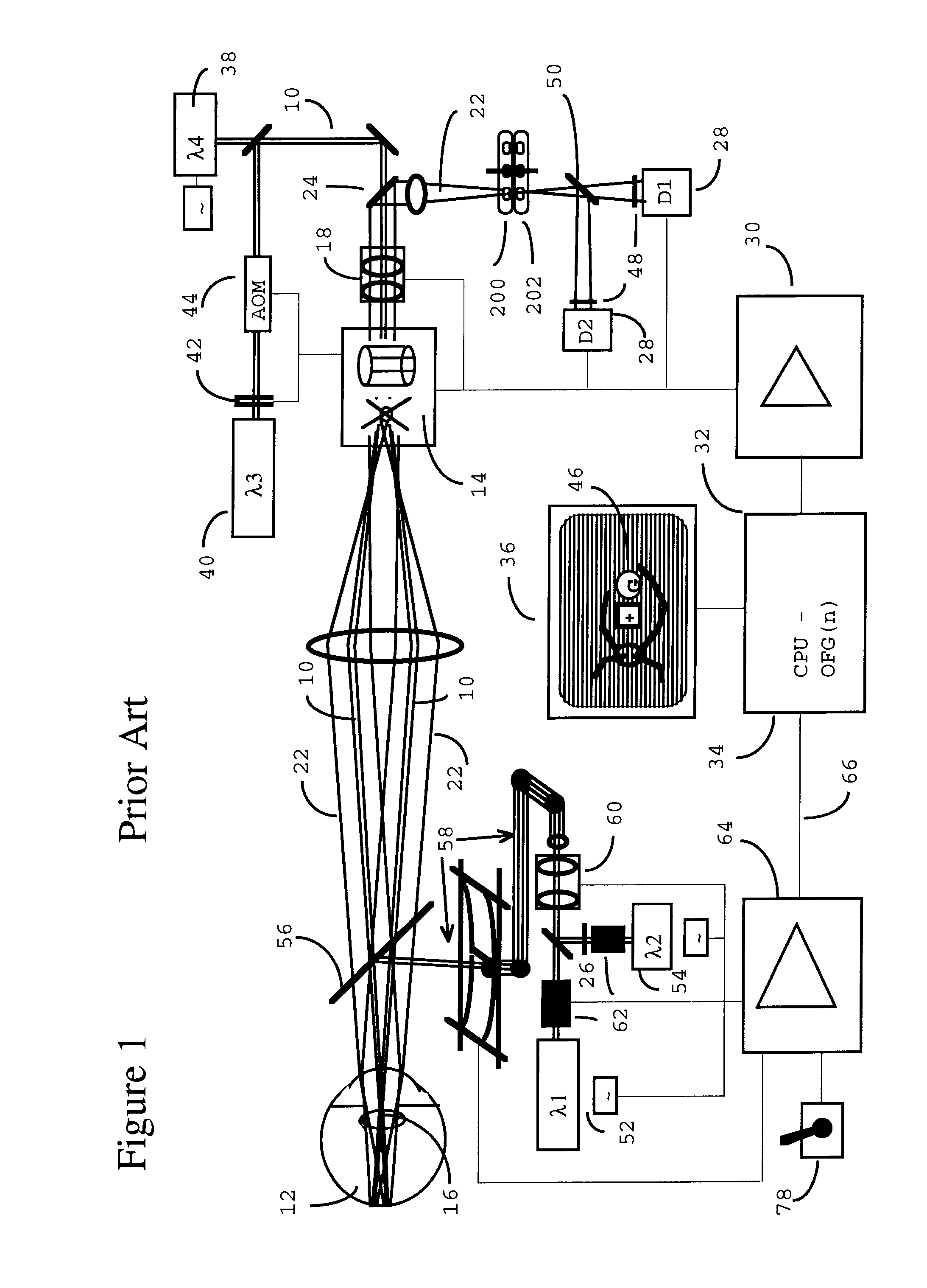
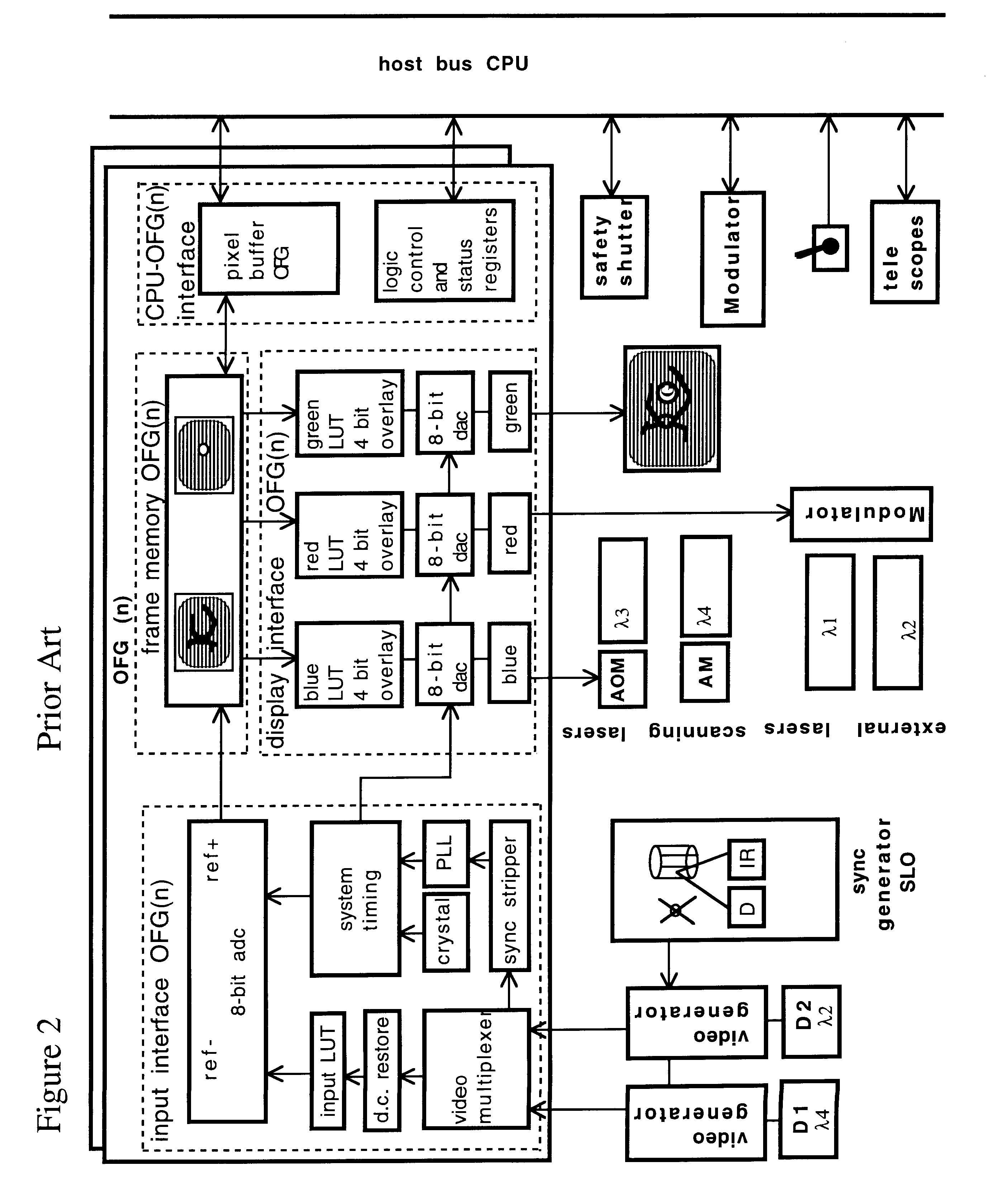
An embodiment of the confocal scanning laser ophthalmoscope for delivery of therapeutic laser to the retina is illustrated in FIGS. 1 and 2 (Van de Velde). The principles of scanning laser ophthalmoscopy are described in detail in the prior art (Pomerantzeff, Saban, Webb). Two additional possibilities for spatial modulation of therapeutic lasers are illustrated in FIGS. 3 and 4.

I. Summary of Prior Art

A confocal scanning laser ophthalmoscope (cSLO) can be optically coupled with multiple external diagnostic or therapeutic laser sources 52, 54 with the help of an appropriate beamsplitter 56. For cSLO imaging, an infra-red diode laser 38 e.g. 792 nm or 830 nm is preferred. For cSLO psychophysics and microperimetry a visible wavelength e.g. 532 nm or 633 nm laser 40 is convenient. The 532 nm wavelength has a superior visibility, especially during photodynamic therapy employing 664 nm or 689 nm laser light. Microphotocoagulation and photodynamic therapy use various wavelength sources 52 b...


PUM


Abstract

A combination of a scanning laser ophthalmoscope and external laser sources (52) is used for microphotocoagulation and photodynamic therapy, two examples of selective therapeutic laser. A linkage device incorporating a beamsplitter (56) and collimator-telescope (60) is adjusted to align the pivot point (16) of the scanning lasers (38, 40) and external laser source (52). A similar pivot point minimizes wavefront aberrations, enables precise focusing and registration of the therapeutic laser beam (52) on the retina without the risk of vignetting. One confocal detection pathway of the scanning laser ophthalmoscope images the retina. A second and synchronized detection pathway with a different barrier filter (48) is needed to draw the position and extent of the therapeutic laser spot on the retinal image, as an overlay (64). Advanced spatial modulation increases the selectivity of the therapeutic laser. In microphotocoagulation, an adaptive optics lens (318) is attached to the scanning laser ophthalmoscope, in proximity of the eye. It corrects the higher order optical aberrations of the eye optics, resulting in smaller and better focused applications. In photodynamic therapy, a spatial modulator (420) is placed within the collimator-telescope (60) of the therapeutic laser beam (52), customizing its shape as needed. A similar effect can be obtained by modulating a scanning laser source (38) of appropriate wavelength for photodynamic therapy.

Description

1. Field of InventionThe invention relates generally to instruments and methods for examining and treating the eye and specifically to various kinds of ophthalmoscopes equipped with laser sources for the purpose of applying a therapeutic laser beam to the retina of an eye.2. Description of Prior ArtOphthalmoscopes, exemplified by the biomicroscope, are combined with a non-scanning therapeutic laser source for the purpose of retinal photocoagulation. Usually, a contact glass is placed on the cornea to be able to view the retina with the biomicroscope, and a mirror is used for reflecting the therapeutic laser beam onto the desired retinal location through a small part of the pupillary area. Importantly, the retina is illuminated with a strong visible light, and it is observed through different parts of the pupillary area to avoid reflexes, an arrangement that is known as Gullstrand's principle of ophthalmoscopy. Such optical configuration makes the art of precise focusing of a therape...

Claims


Application Information

Patent Timeline
Patent Type & Authority Patents(United States)
IPC IPC(8): A61F9/007A61F9/008A61B17/22A61B3/12A61F9/01
CPCA61F9/008A61F9/00821A61B3/1025A61B2017/22087A61F2009/00863A61F2009/00872A61F2009/00897
Inventor VAN DE VELDE, FRANS J.
Owner VAN DE VELDE JOZEK F
Why Eureka
Try Eureka