Magnetic recording device

a recording device and magnetic technology, applied in the field of magnetic recording devices, can solve problems such as mechanical failure of the spindle bearing

Inactive Publication Date: 2001-02-27
WESTERN DIGITAL TECH INC
View PDF21 Cites 17 Cited by
  • Summary
  • Abstract
  • Description
  • Claims
  • Application Information

AI Technical Summary

Problems solved by technology

Continued operation of the recording device in the presence of the ac

Method used


Image

  • Magnetic recording device
  • Magnetic recording device
  • Magnetic recording device

Examples


Embodiment Construction

Two lubricant compositions were tested for stability. Each lubricant composition comprised the copolymer amine of the present invention (copolymer of phenylnapthylamine and dioctyldiphenylamine) and one had TCP. Each lubricant composition was placed in a 50 ml pyrex beaker and covered with tin foil. A 5 mm hole in the center of the tin foil allowed periodic sampling for analysis. Clean ball bearings were immersed in the composition. The compositions were monitored by UV spectroscopy, and failure was detected by sudden absorbance between 200-300 nm. The results are shown in the table below. It can be seen from the results that the composition having both the polymeric amine and the TCP exhibited synergistic improvement in stability.

Although this invention has been described with respect to specific embodiments, the details thereof are not to be construed as limitations for it will be apparent that various embodiments, changes and modifications may be resorted to without departing fro...


PUM

PropertyMeasurementUnit
Speedaaaaaaaaaa

Abstract

The invention relates to a magnetic recording data storage device which can operate effectively at high rotational speeds. The magnetic recording device of the present invention comprises (a) a magnetic recording disk, (b) a spindle motor, (c) a head supported on an air bearing carrier, and (d) an actuator connected to the head carrier for moving the head across the rotating disk. The spindle motor comprises ball bearings lubricated by a grease comprising a polymeric amine and bis or tris (alkyl phenyl)phosphate. The grease improves rotational operation of the disk drive.

Description

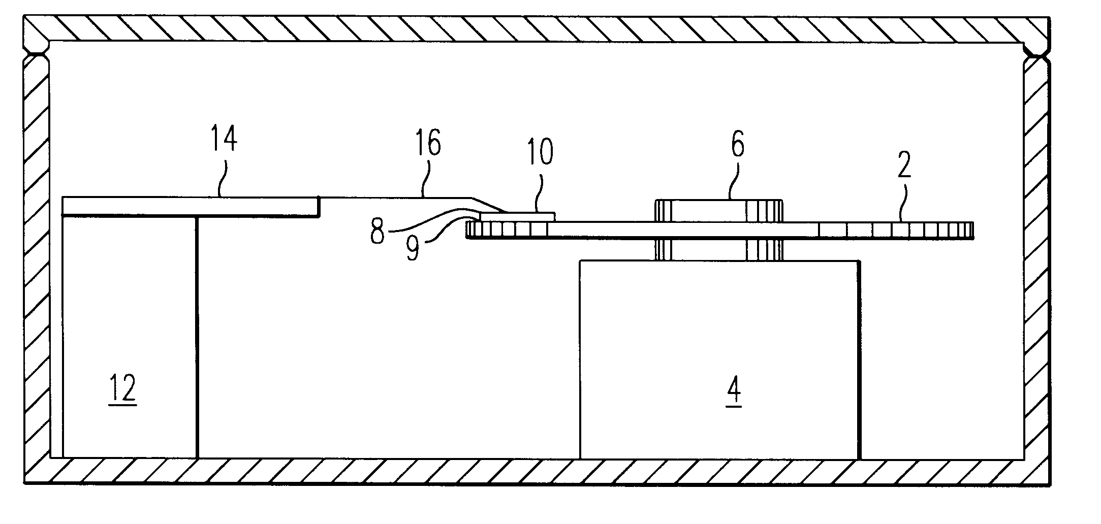
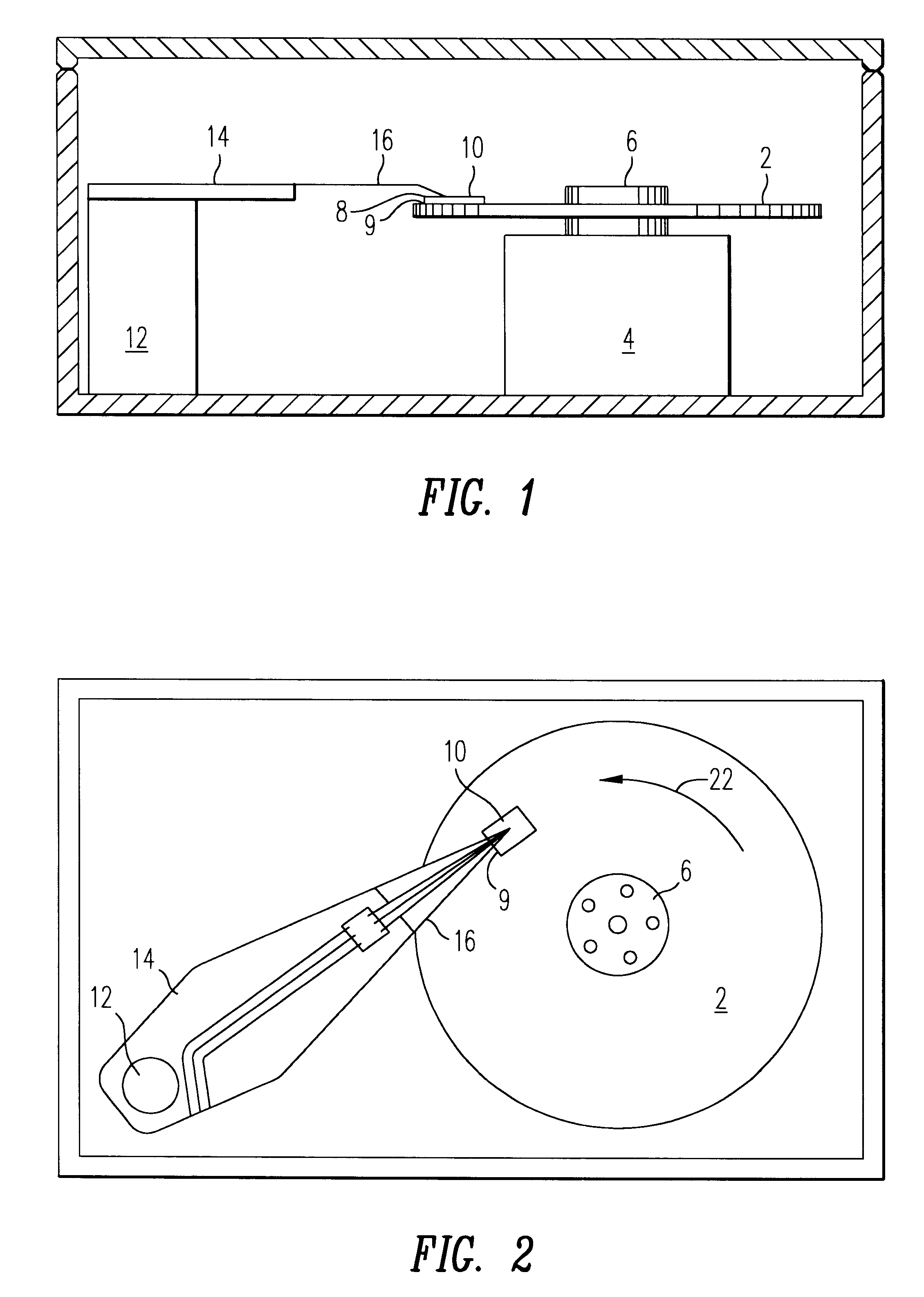
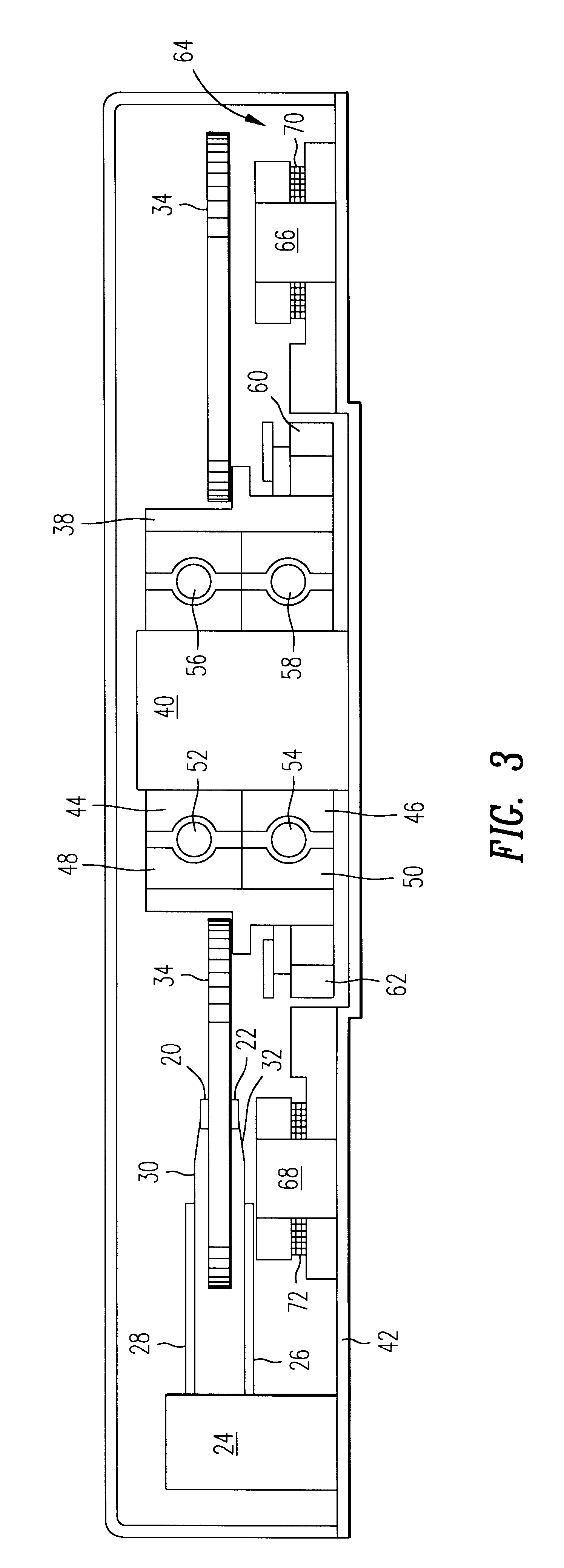
1. Field of the InventionThe present invention relates to a magnetic recording device having an improved spindle motor lubricant.2. Description of the Background ArtCurrent growth rates for digital magnetic recording data storage industry show a significant annual increase in recording densities and transfer rate and a decrease in seek time. To continue on this growth rate curve, the recording industry is being forced to make a number of significant changes in the design and operation of the magnetic recording device. Digital magnetic recording devices for data storage generally comprise a thin film magnetic recording disk, a spindle motor for rotating the disk, and a head or transducer which is moved along or above the surface of the rotating disk to read and write information on the disk. The thin film magnetic recording disks generally comprise a substrate, a magnetic layer such as a cobalt-based metal alloy, a protective amorphous carbon layer and a layer of perfluoropolyether d...

Claims


Application Information

Patent Timeline
IPC IPC(8): C10M169/00G11B19/20G11B5/02
CPCC10M169/00G11B19/2009C10M137/04C10M149/12C10M2217/00C10M2217/02C10M2217/04C10M2223/04C10M2223/041C10M2223/042C10N2240/20C10N2240/201C10N2240/202C10N2240/203C10N2240/204C10N2240/205C10N2040/14C10N2040/175C10N2040/18C10N2040/185C10N2040/16C10N2040/17G11B5/02
Inventor KARIS, THOMAS EDWARDNAGARAJ, HOLAVANAHALLY S.
Owner WESTERN DIGITAL TECH INC
Why Eureka
Try Eureka