Data switch
- Summary
- Abstract
- Description
- Claims
- Application Information
AI Technical Summary
Benefits of technology
Problems solved by technology
Method used
Image
Examples
Embodiment Construction
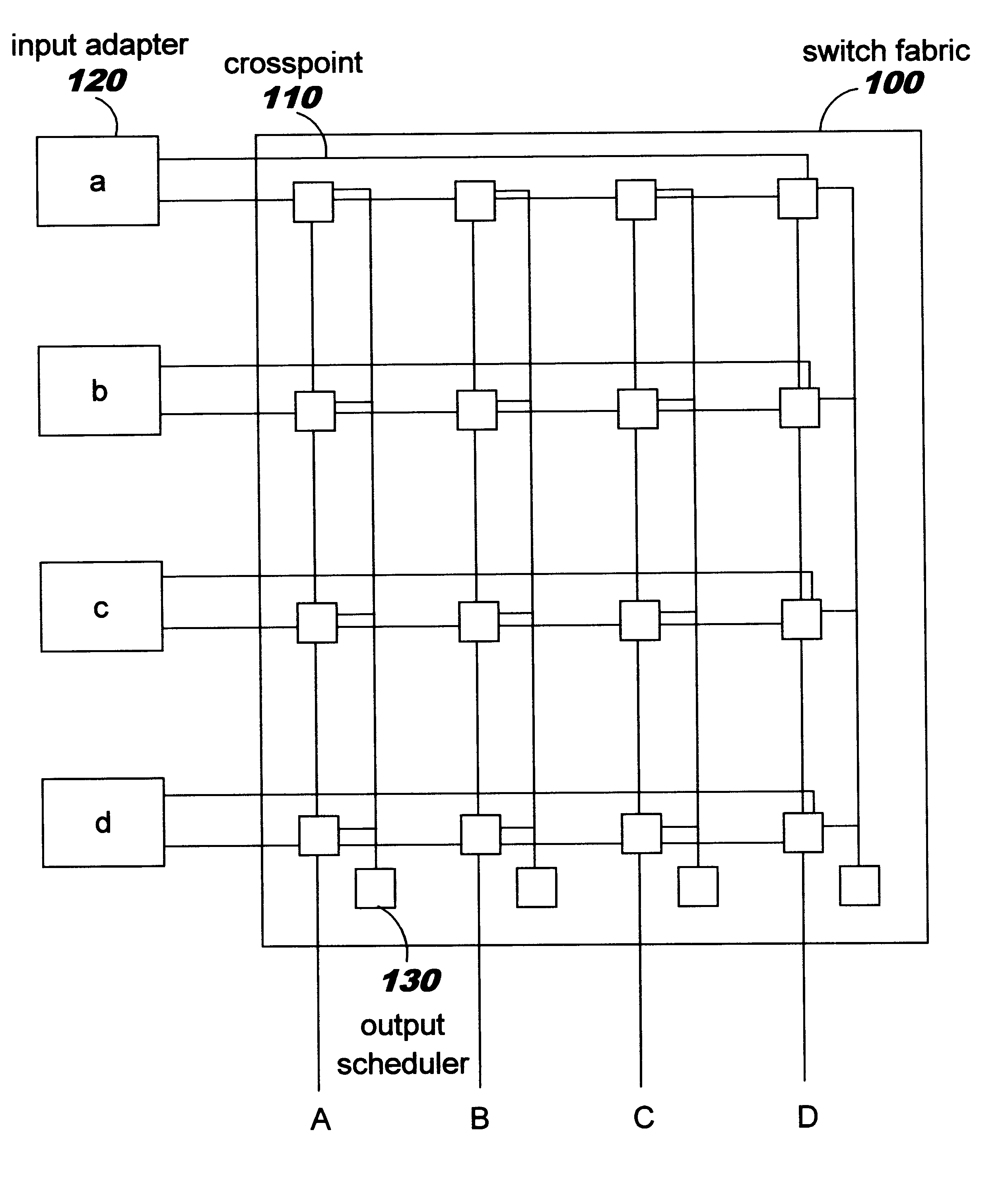
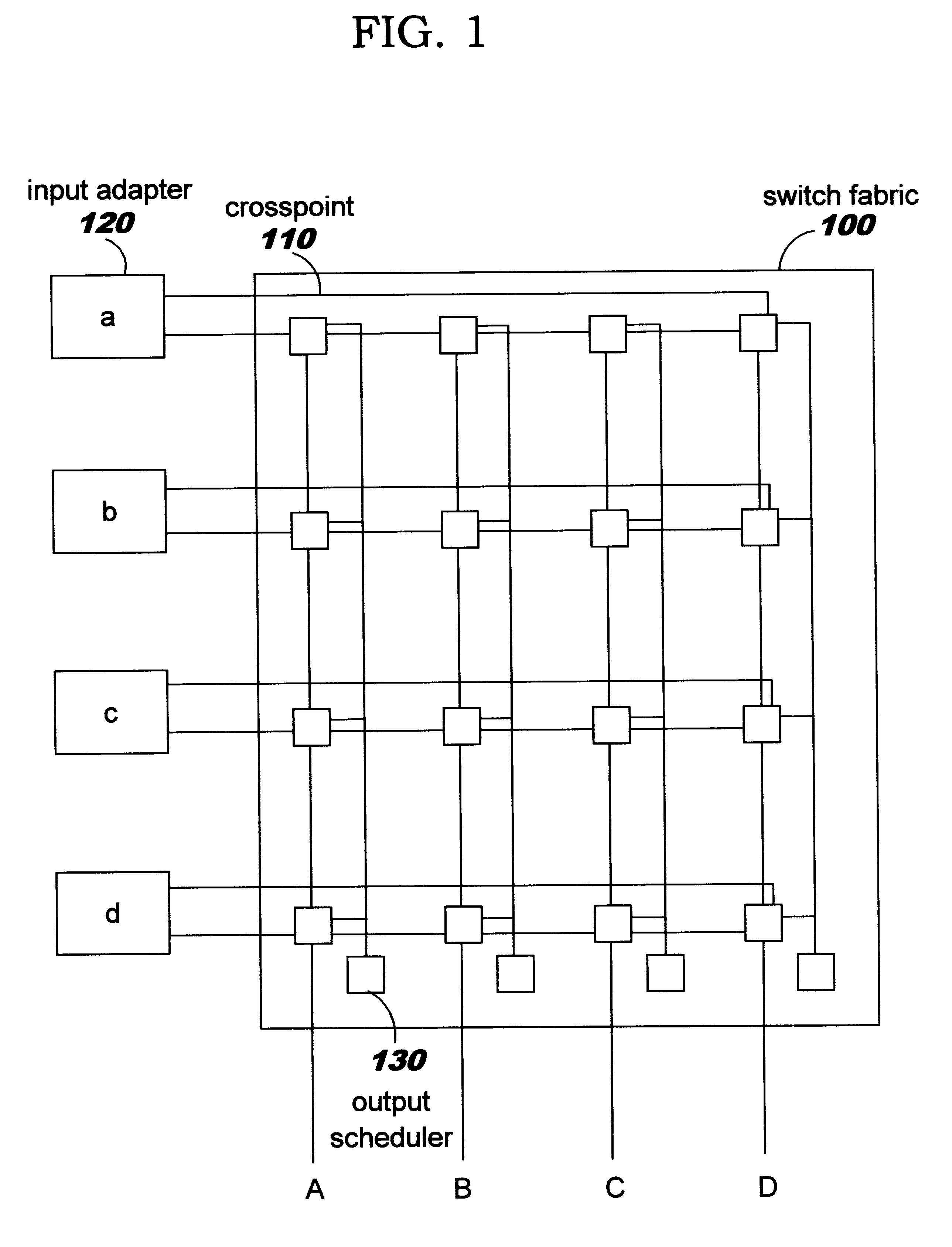
FIG. 1 is a schematic diagram showing a packet switch having four inputs denoted a, b, c, d and four outputs, A, B, C, D. It will be clear to those skilled in the art how the apparatus to be described below may be modified to accommodate different numbers of inputs and outputs.
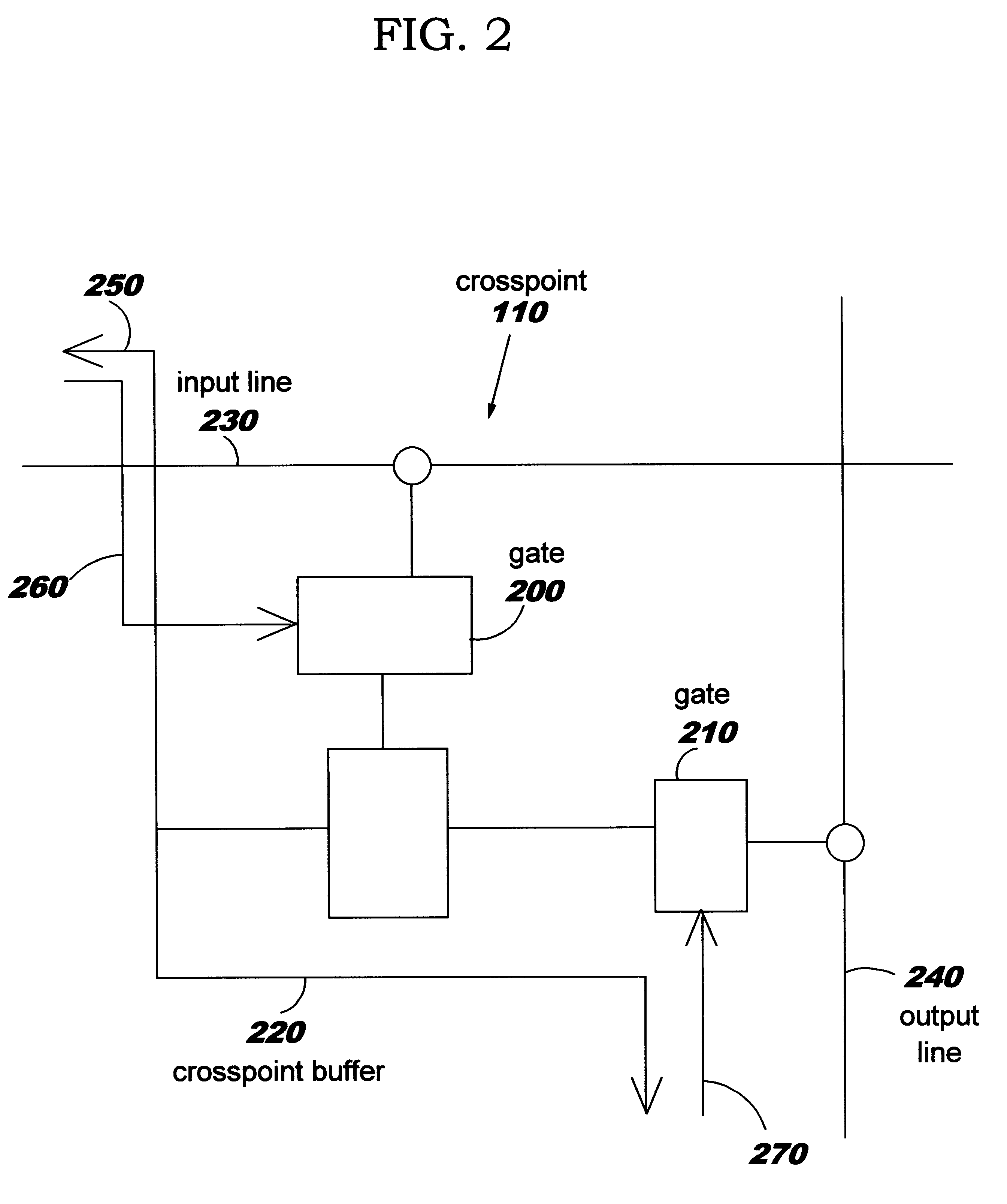
The switch includes a crossbar switch fabric 100 through which data packets can be transmitted between any one of the inputs and any one of the outputs via crosspoints 110. An input adapter 120 is provided at each input which includes an input queue mechanism, which will be described in more detail below, for temporarily storing data packets whilst they are waiting to be transmitted through switch fabric 100. It will be understood that outputs A,B,C, and D are connected to output adapters (not shown). Output schedulers 130 are provided to schedule the transfer of data packets from the crosspoints 110 to the outputs as will be described in more detail below.
It will be appreciated that in practical embodiments, ...
PUM
 Abstract
Description
Claims
Application Information
 - R&D
- Intellectual Property
- Life Sciences
- Materials
- Tech Scout
- Unparalleled Data Quality
- Higher Quality Content
- 60% Fewer Hallucinations
Browse by: Latest US Patents, China's latest patents, Technical Efficacy Thesaurus, Application Domain, Technology Topic, Popular Technical Reports.
© 2025 PatSnap. All rights reserved.Legal|Privacy policy|Modern Slavery Act Transparency Statement|Sitemap|About US| Contact US: help@patsnap.com


