Method and device for laminar flow on a sensing surface

a technology of sensing surface and laminar flow, which is applied in the direction of withdrawing sample devices, nanotechnology, material testing goods, etc., can solve the problems of limiting the ability to resolve fast reaction kinetics, increasing sample consumption, and lag in both rise and fall of sensorgrams

Inactive Publication Date: 2001-03-13
GE HEALTHCARE BIO SCI CORP
View PDF13 Cites 238 Cited by
  • Summary
  • Abstract
  • Description
  • Claims
  • Application Information

AI Technical Summary

Problems solved by technology

Such dispersion results in a time lag in both the rise and fall of the sensorgram at the beginning and end of sample introduction.
These so-called "rise and fall times" limit the ability to resolve fast reaction kinetics (i.e., interactions with high rate constants).
Unfortunately, increasing the flow rate means increased sample consumption.
There are also practical and design limitations in terms of, for example, liquid pressure which provide an upper limit for the flow rate.
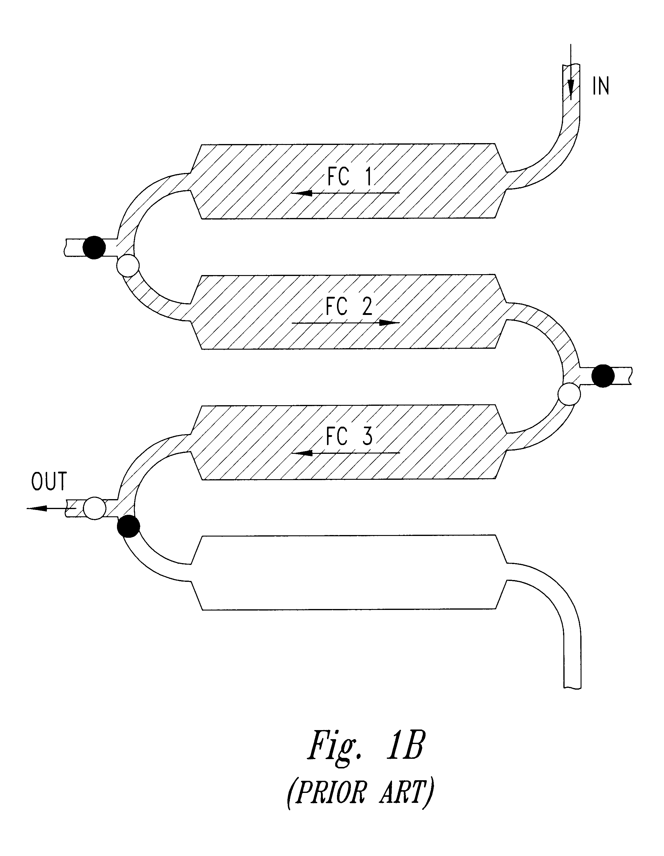
In addition, temperature variations between flow cells can negatively impact sample analysis.
Due to physical separation of the flow cells, and hence the sensing surfaces, temperature fluctuations between flow cells can be a source of measurement error.
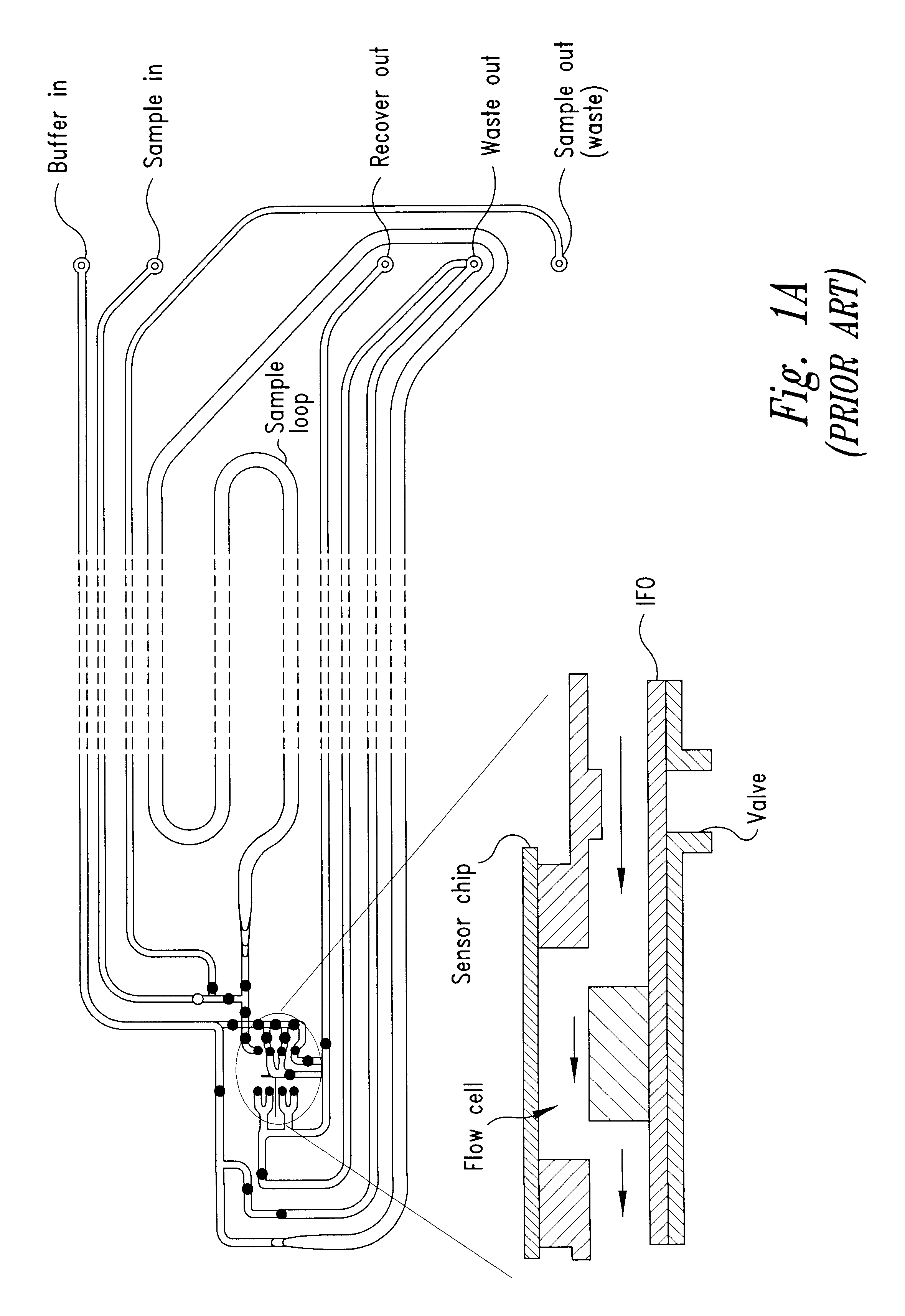
Further, the flow cells depicted in FIGS. 1A and 1B do not permit controlled sample delivery to discrete areas within a single flow cell, nor do they allow immobilization of different ligands to discrete sensing areas within a single flow cell.
Rather, such modifications are only achieved within separate flow cells, and thus are accompanied by the limitations as noted above.
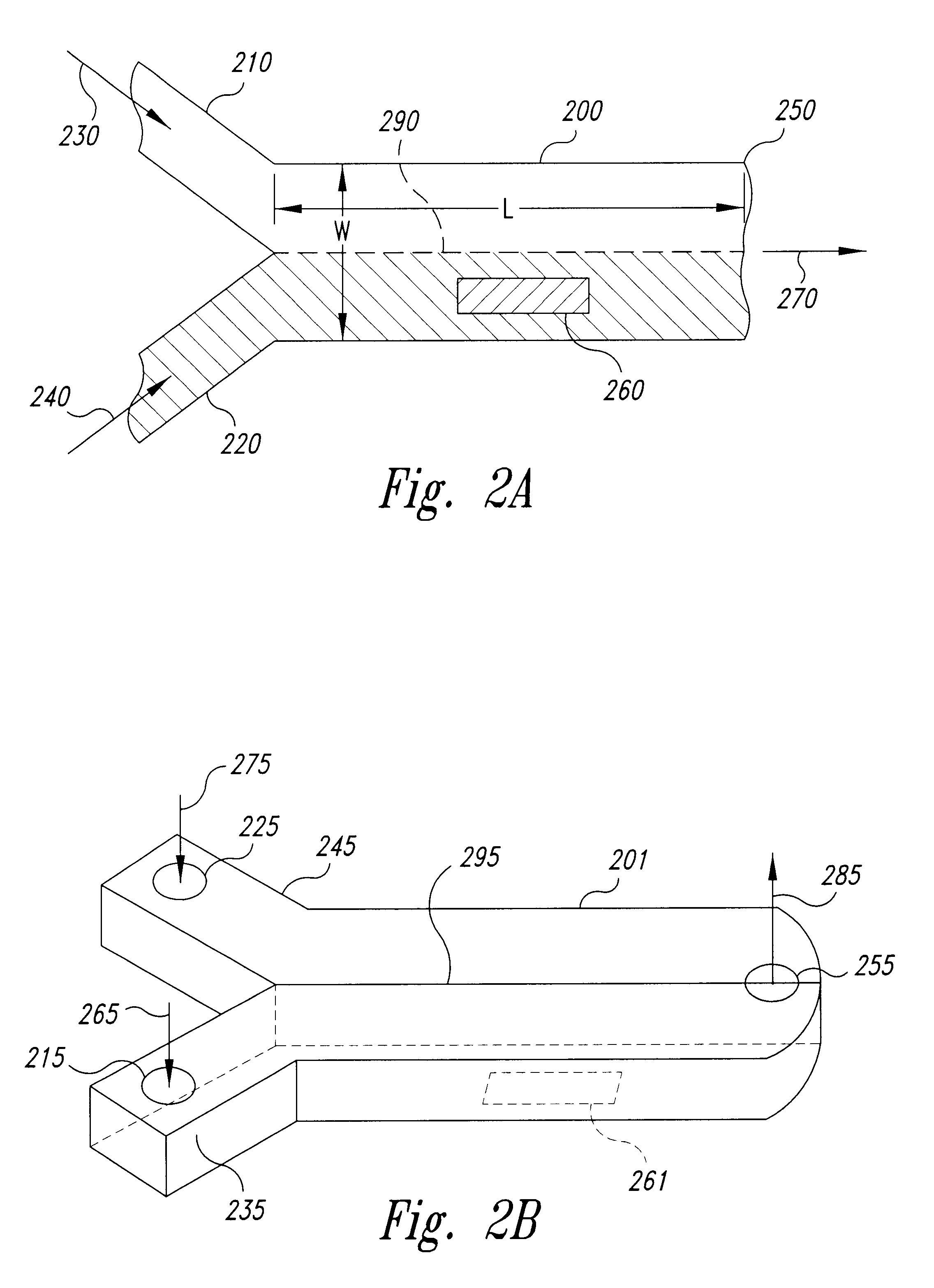
In addition, directing a sample flow within a flow cell using a separate flow (e.g., a buffer) requires that the diffusion of the sample be limited to the region close to the interface between the two flows.
Otherwise, diffusion will interfere with the directionality of the sample flow and, rather than two (or more) distinct flows, a "smear" of sample and buffer will result.

Method used


Image

  • Method and device for laminar flow on a sensing surface
  • Method and device for laminar flow on a sensing surface
  • Method and device for laminar flow on a sensing surface

Examples


example 1

Representative Flow Cells

This example discloses representative flow cells, as well as the use thereof in the context of this invention. In particular, different Y and .PSI. flow cells are illustrated.

A representative Y flow cell uses the inlets to flow channels 1 and 2, and the outlet to flow channel 2 of a commercially available IFC 4 for a BIAcore 1000 system (BIACORE AB, Uppsala, Sweden). Referring to FIG. 15, sample flow enters Y flow cell 1500 from inlet 1510, and the buffer enters the Y flow cell from inlet 1520. Both sample and buffer exit the Y flow cell via outlet 1530. Both sample and buffer flows are directed into the flow cell by cutting an additional channel in the IFC 4 to allow both sample and buffer to be run through the flow cell simultaneously. The volume of the Y flow cell is 180 nl (i.e., three times the volume of commercially available BIAcore flow cells).

A representative one dimensional ("1D") .PSI. flow cell is depicted in FIG. 16, where sample flow enters .PS...

example 2

Diffusion of Fluid Flows

This example summarizes experiments directed to diffusion of fluid flows as they pass through the representative .PSI. flow cell of Example 1. As mentioned above in the context of FIG. 6, directing fluid flows within a flow cell under laminar flow requires diffusion of the sample to be limited to a region close to the interfere between the flows. If this is not the case, diffusion will interface with the directionality of the sample flow and, rather than distinct flows, a "smear" of flows will result.

In this experiment, diffusion width is determined after about 0.3 seconds, which is the time it takes to transport a molecule through the flow cell of the BIAcore instrument at a flow rate of 10 .mu.l / min. The diffusion width (see FIG. 17A) was measured as the width of a color change of an indicator as measured by ocular inspection with a Panasonic WV-Ks152 video camera and a microscope mounted to the work processor. The diffusion width for different contact time...

example 3

Ion Exchange / On-Line Dialysis

The FIG. 20 shows how an ion exchange or an on-line dialysis may be performed employing the techniques of this invention. FIGS. 20A and 20B illustrate ion exchange with low ion concentration in the adjacent buffer. FIGS. 20C and 20D demonstrate ion exchange when the ion concentration in the adjacent buffer is high. The panels shown in FIG. 20 are for two different flow rates: 10 .mu.l / min in FIGS. 20A and 20C, and 100 .mu.l / min in FIGS. 20B and 20D. The distance between the two interfaces is 12 .mu.m in 20A, 20B, 20C and 20D. Referring to FIG. 20A, the flow rate is 10 .mu.l / min and the concentration of salt and protons for the adjacent buffer is low. The salt concentration in the sample flow decreases to 10% and the proton concentration decreases to 6% of the original concentration. In FIG. 20B the flow rate is 100 .mu.l / min, the salt concentration in the sample flow decreases to approximately 30% of the original concentration, and the proton concentrati...


PUM

PropertyMeasurementUnit
surface areaaaaaaaaaaa
volumeaaaaaaaaaa
lengthaaaaaaaaaa

Abstract

Methods and devices are provided for controlling a fluid flow over a sensing surface within a flow cell. The methods employ laminar flow techniques to position a fluid flow over one or more discrete sensing areas on the sensing surface of the flow cell. Such methods permit selective sensitization of the discrete sensing areas, and provide selective contact of the discrete sensing areas with a sample fluid flow. Immobilization of a ligand upon the discrete sensing area, followed by selective contact with an analyte contained within the sample fluid flow, allows analysis by a wide variety of techniques. Sensitized sensing surfaces, and sensor devices and systems are also provided.

Description

The present invention generally relates to the control of a fluid flow over a sensing surface within a flow cell and, more specifically, to the use of laminar flow techniques to position a fluid flow over one or more discrete sensing areas within a flow cell, as well as the use thereof in the preparation of sensing surfaces and in analytical methods, devices and systems related thereto.BACKGROUND OF INVENTIONInstrumentation for real-time Biomolecular Interaction Analysis (BIA) is commercially available from Biacore AB (Uppsala, Sweden) under the trade name BlAcore (hereinafter "the BIAcore instrument"). The BIAcore instrument employs surface plasmon resonance (SPR) to investigate interactions between molecules at the surface of a sensor chip, and includes a processing unit with liquid handling and optical systems, a sensor chip, and a computer for control and data evaluation. One molecule, referred to as the "ligand," is immobilized on the surface of the sensor chip, and the other m...

Claims


Application Information

Patent Timeline
Patent Type & Authority Patents(United States)
IPC IPC(8): G01N21/03G01N21/05
CPCB01L3/502776B82Y30/00G01N21/05G01N21/553G01N21/648B01J2219/00511Y10T436/2575B01J2219/00585B01J2219/00596B01J2219/00605B01J2219/0063B01J2219/00637B01J2219/00657B01J2219/00659B01J2219/00675B01J2219/00722B01J2219/00725B01J2219/00734B01L2200/0636B01L2200/12B01L2300/0636B01L2300/0877G01N2021/058Y10S366/03Y10S366/01G01N2021/0346Y10T436/25625Y10T436/11Y10T436/117497Y10T436/25B01J2219/00572
Inventor MALMQVIST, MAGNUSROOS, H.ANG.KANSJOLANDER, STEFANTIDARE, MATTIASSJODIN, H.ANG.KANST.ANG.LBERG, RALPH
Owner GE HEALTHCARE BIO SCI CORP
Why Eureka
Try Eureka