
Method and system for welding railroad rails

a technology for railroad rails and rails, applied in auxiliary welding devices, soldering devices, ways, etc., can solve the problems of arc blowing through, arc blowing through or blowing through holes that are not desirable, and tend to create cutting actions, etc., to achieve the effect of convenient implementation

Inactive Publication Date: 2001-03-13
LINCOLN GLOBAL INC
View PDF4 Cites 37 Cited by
  • Summary
  • Abstract
  • Description
  • Claims
  • Application Information

AI Technical Summary

Benefits of technology

The selected path of the welding torch is a square weave. In the path, the torch or welding wire moves perpendicularly to the end walls of the rails. This movement is accomplished by an angular swinging action of the torch directing current to the welding wire for the welding process. Upon reaching the side wall of the rail, the torch maintains its angle pointed toward the joint between the plates and rail end and then moves parallel to the side wall of the rail. After moving a short predetermined distance along the rail end, the robotic mechanism stops the torch carrying the welding wire. Thereafter, the torch and welding wire is pivoted or swung back toward the opposite rail. When the torch reaches the opposite rail, the angle of the torch carrying the welding wire is equal but opposite to the torch angle at the other side. Thereafter, a short forward movement is made by the torch and the cycle is repeated to create a selected welding pattern or path. By using this square wave, swinging or pendulum welding action, together with a maintenance of the height of the torch from the backing plate, advantages of the various aspects of the present invention are obtained.
An automatic controller moves the torch in the selected path or pattern described in detail above. This automatic controller and the robot is responsible for movement of the torch and can adjust the torch movement based upon feedback from the welding operation. This is standard technology for controlling the movement of the electrode by the robotic mechanism for moving the torch through the selected path or pattern. When the current is sensed to be below a set value, an arc blow through is detected. When this occurs, the automatic controller in the robot mechanism moves the torch in the reverse direction back to the previous decision point or for a short distance in the selected pattern. The welding wire is melted and fills the blow through opening or hole so that the welding process can continue uninterrupted across the previously blown through hole in the backing plate. The torch returns to its movement normal pattern and is moved back across the previous blow through location. The molten metal ahead of the torch fills any hole created by the blow through. By permitting the welding process to continue a puddle of weld metal is allowed to build up under the arc. The metal fills the hole created by the blow through so that the reversal of the torch for a short time or distance or to a prior decision point fills the blow through hole at once. Thus, the blow through defect is overcome and the welding process continues. In summary, as the torch is swung back and forth, the current is monitored. If the current drops below a relatively low value, indicative of a blow through, the swinging action of the torch is reversed to fill the blow through so that the torch can resume its normal movement along the selected pass. This same action can occur as the torch is moving longitudinally between the portions of the selected pattern defined by a swinging action of the torch; however, these branches are so short and require a blow through to fill the fillet area. The invention assures at least a blow through in successive longitudinal movements on each fillet of the gap. If a blow through is detected, it is recorded. In this manner, a blow through can be forced in the next longitudinal branch on the same side of the gap when there has been no sensed blow through.
In accordance with another aspect of the present invention, there are a series of decision points in the selected path as the torch moves at an angle along the fillet between the backing plate and the end of one of the rails. At each of these decision points, a determination is made whether an arc blow through, forced or unforced, has occurred. If there has been no arc blow through in two adjacent decision points in one longitudinal branch of the fillet weld, the voltage of the power supply is decreased to reduce the footprint of the arc causing a concentrated arc and thus a forced blow through. By using this aspect of the invention, in combination with the other aspect of the invention, an improved root pass is created along the upper level of the consumable backing plate and in the fillet areas.
In accordance with still a further object of the present invention, there is provided a method and system as defined above, which method and system is easily implemented with standard robotic control mechanisms so a quality root pass can be deposited to fill the gap between the ends of the railroad rails.

Problems solved by technology

By using a thin consumable backing plate, there is a possibility of arc blow through whereby the arc penetrates completely through the backing plate.
Such arc blow through or blow through hole is not desirable as the wire moves transversely across the backing plate.
The disadvantage of this blow through is that it tends to create a cutting action as the torch swings transversely across the insert.
This causes an increase in the resistance of the welding operation.

Method used


Image

  • Method and system for welding railroad rails
  • Method and system for welding railroad rails
  • Method and system for welding railroad rails

Examples


Embodiment Construction

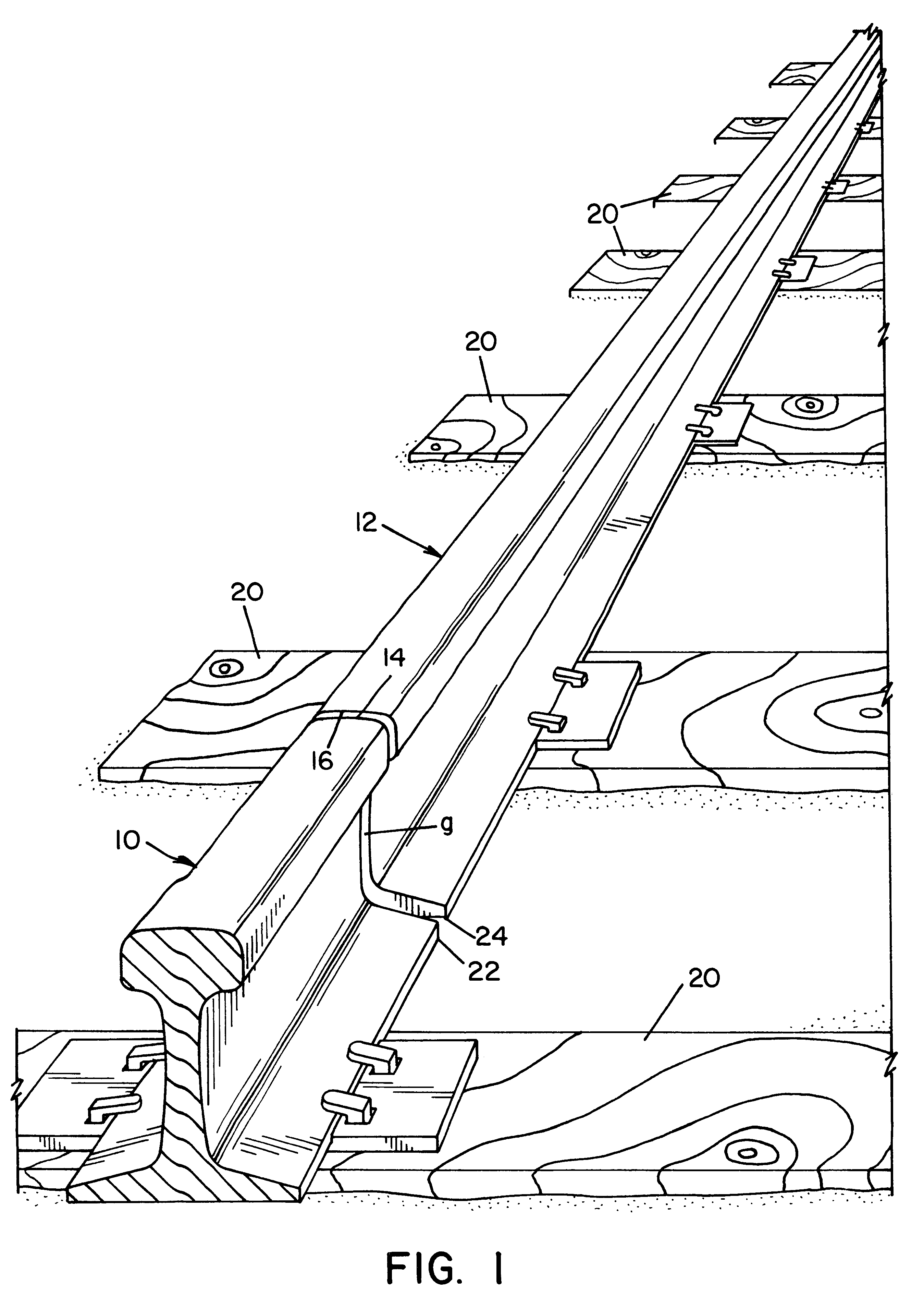
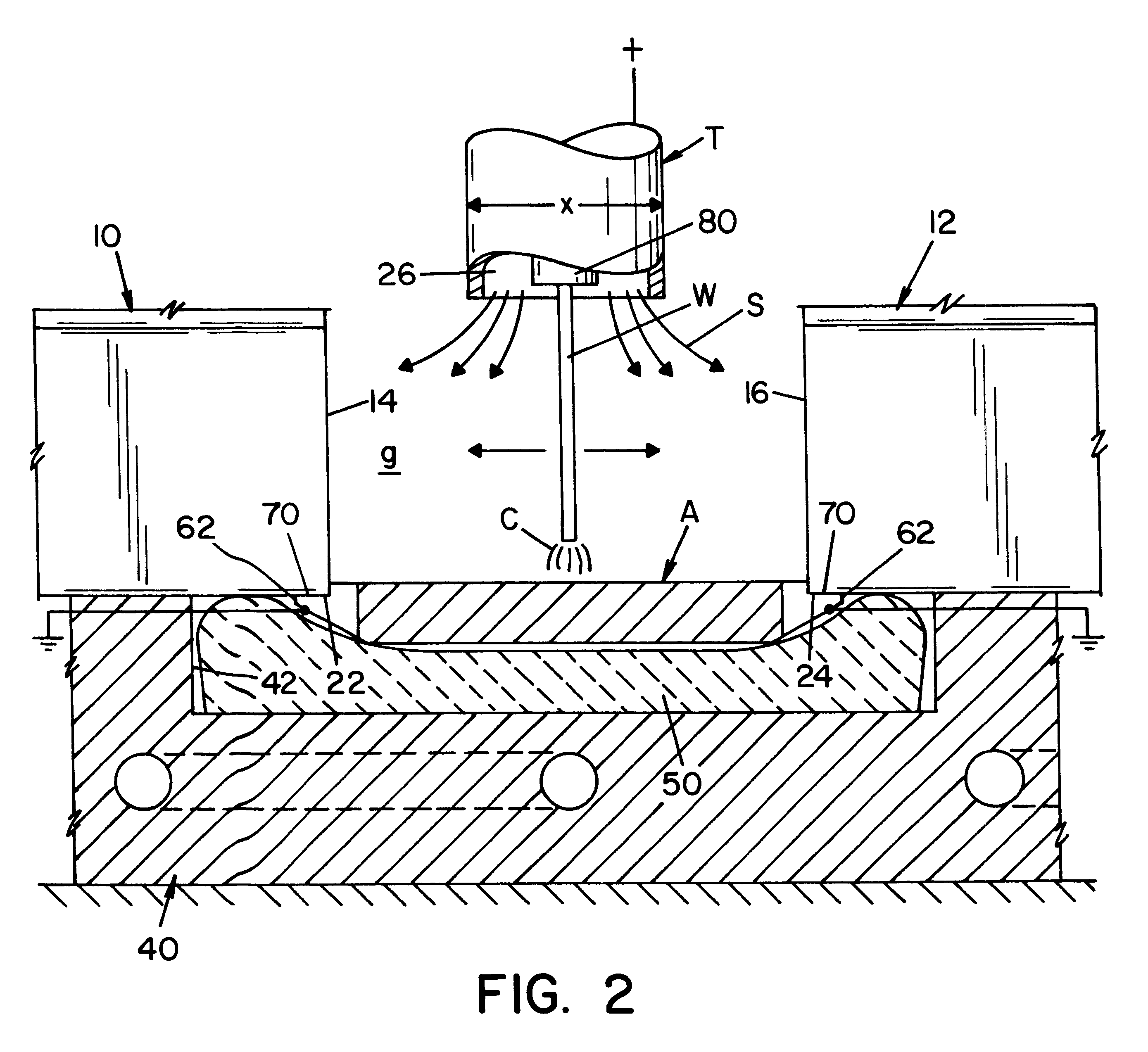
Referring to the drawings wherein the showings are for the purpose of illustrating a preferred embodiment of the invention only, and not for the purpose of limiting same, FIG. 1 shows two spaced railroad rails 10, 12 mounted on railroad ties 20 and provided with a gap g between oppositely facing surfaces 14, 16, respectively. The gap g is provided between the rails for the purposes of joining the rails in the field by using a robotic control mechanism to perform a welding operation as illustrated in Morlock U.S. Pat. No. 5,773,779 and Morlock U.S. Pat. No. 5,877,468. Gap g is above flat base portions 22, 24, which portions are used to support a lower backing plate A, positioned below flat bases 22, 24 to define the root pass area. A root pass is the first layer of molten metal to be deposited by the electric arc welding process in gap g. As shown in FIGS. 2-4, backing plate A is supported in the longitudinally extending recess 42 in copper shoe 40 so that recess extends between rail...


PUM

PropertyMeasurementUnit
Lengthaaaaaaaaaa
Currentaaaaaaaaaa
Electric potential / voltageaaaaaaaaaa

Abstract

A method and system of depositing molten metal from an advancing welding wire to form a root pass of weld metal in the bottom of a gap between first and second metal members having generally flat base elements joined by a metal backing plate extending between said base elements, which method and system includes passing welding current between the welding wire and the metal members from a power supply to create a heat generating welding arc, moving the welding wire in a given direction along selected path over the backing plate, sensing a blow through of the backing plate by the welding arc, reversing said given direction of said welding wire for a short distance when a blow through has been sensed and then, resuming movement of said welding wire in said given direction along the selected path.

Description

The present invention relates to a method and system for welding the spaced ends of rails and more particularly to welding two spaced railroad rails by using an electric arc welding process.INCORPORATION BY REFERENCEThrough the years a tremendous amount of effort has been devoted to joining spaced railroad rails by some type of butt welding process. Assignee of the present application has issued patents Morlock U.S. Pat. No. 5,773,779 and Morlock U.S. Pat. No. 5,877,468, which patents are incorporated by reference herein as showing the background of the invention. These patents relate to an electric arc welding method and system for joining the ends of two spaced rails utilizing a backing between the flat bases of the rails so that the root pass or first welding layer is deposited on the backing plate spanning the gap between the rail ends as the plate is consumed. These two patents disclose in detail the total welding process above the root pass for initially joining the ends of th...

Claims


Application Information

Patent Timeline
IPC IPC(8): B23K9/02B23K9/035B23K37/06B23K9/00B23K9/038B23K9/12
CPCB23K9/0213B23K9/0216B23K9/035B23K2201/26B23K2101/26
Inventor MUMAW, JAMES W.
Owner LINCOLN GLOBAL INC
Learn More