
Urea pyrolysis chamber and process for reducing lean-burn engine NOx emissions by selective catalytic reduction

Inactive Publication Date: 2001-03-20
CLEAN DIESEL TECHNOLOGIES
View PDF19 Cites 161 Cited by
  • Summary
  • Abstract
  • Description
  • Claims
  • Application Information

AI Technical Summary

Benefits of technology

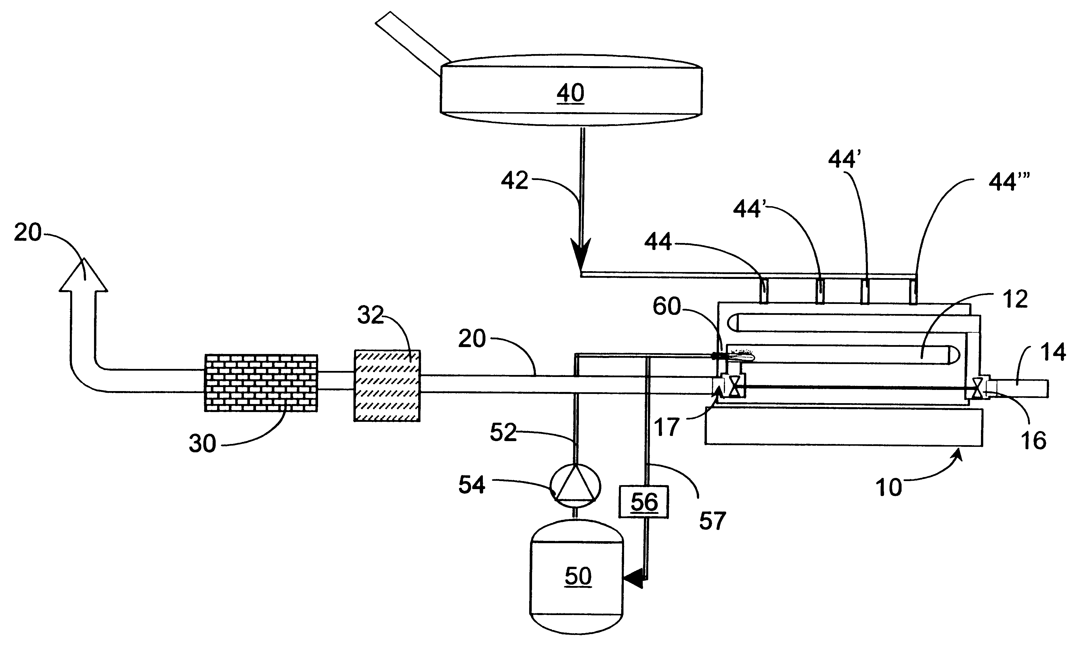
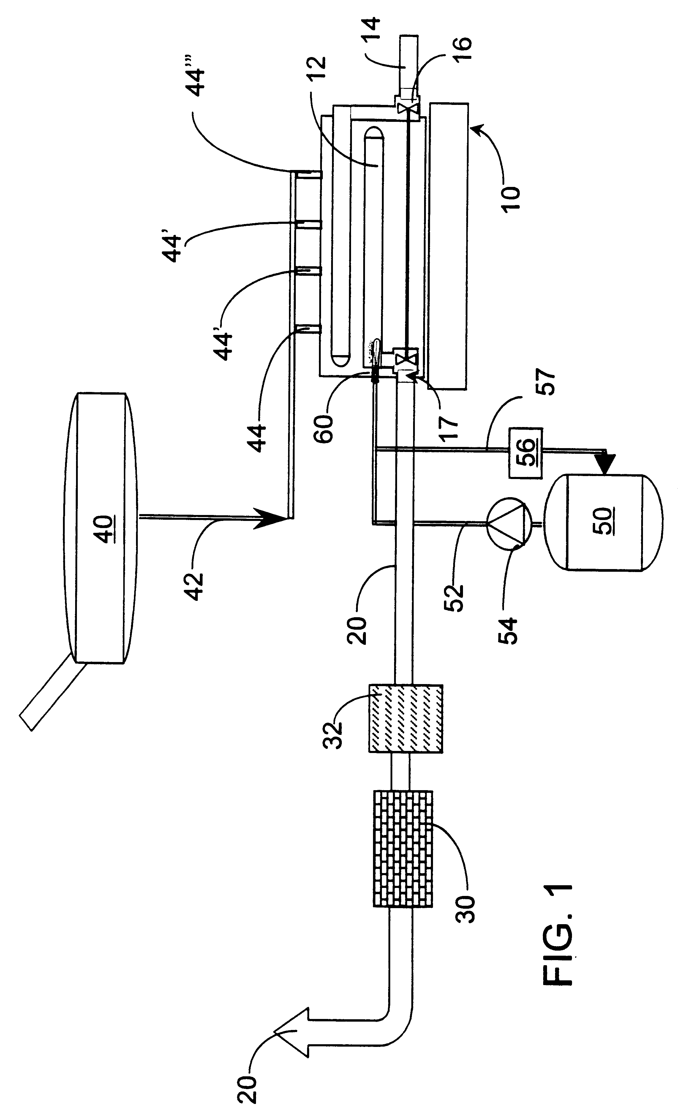
It is an object of the invention to provide a safe, reliable SCR system for reducing NO.sub.x emissions from an internal combustion engine.
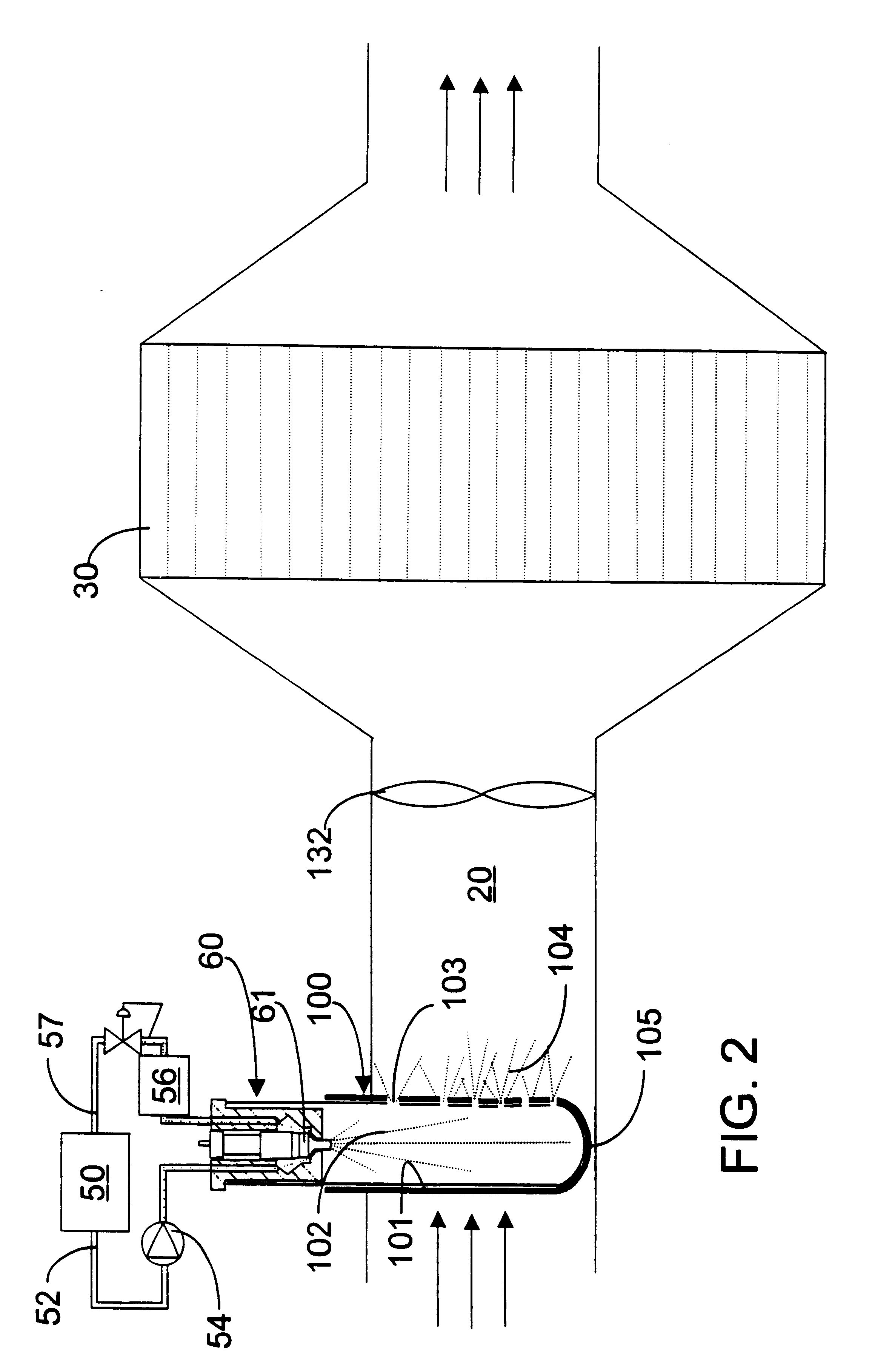
It is yet another specific object of the invention to provide a simple mechanical device for accomplishing the above objects and preferably to enable close coupling of the reagent injection means and the SCR catalyst, thus permitting the placement of urea injection equipment at a greater variety of positions.

Problems solved by technology

Current and proposed regulations challenge manufacturers to achieve good fuel economy and reduce particulates and NO.sub.x.
Lean-burn engines will be necessary to achieve the fuel economy objective, but the high concentrations of oxygen in the exhaust renders typical exhaust gas catalyst systems ineffective for reducing NO.sub.x.
To date, however, SCR has depended on the use of ammonia, which has safety problems associated with its storage and transport.
Urea and other reagents are safer, but have not been practical for many SCR applications--particularly mobile NO.sub.x sources--due to the difficulty in converting them from solid or solution form to active gaseous species, typically NH.sub.j and HNCO radicals.
Hulterman describes a number of technical challenges including clogging of atomizers, decomposition problems and system dynamics.
Urea takes time to break down in hot exhaust gases and may cause nozzle plugging.
Moreover, they employ dilute solutions that require significant heating to simply evaporate the water.
The disclosure notes that if the inside of the catalyzer and the nozzle tip only were coated with the catalyst, corrosion and deposition occurred.
Each of the points of caution by these references about the difficulties of using urea with SCR systems, especially for mobile sources, illustrates the trouble and lack of practical success the art has had and continues to have.

Method used


Image

  • Urea pyrolysis chamber and process for reducing lean-burn engine NOx emissions by selective catalytic reduction
  • Urea pyrolysis chamber and process for reducing lean-burn engine NOx emissions by selective catalytic reduction
  • Urea pyrolysis chamber and process for reducing lean-burn engine NOx emissions by selective catalytic reduction

Examples


Embodiment Construction

In this description, the term "lean-burn engine" is meant to include engines that can be operated with an inlet oxygen concentration greater than the amount required for stoichiometric (or chemically correct) combustion of a hydrocarbon fuel, e.g., at least 1% by weight excess oxygen. The term "engine" is meant in the broad sense to include all combustors which combust fuel to provide heat, e.g., for direct or indirect conversion to mechanical or electrical energy. Internal combustion engines of the Otto, Diesel and turbine types, as well as burners and furnaces, are included and can benefit from the invention. However, since the problems and advantages of successful achievement of reliable NO.sub.x reduction on diesel engines are so pronounced, the diesel engine is used throughout this description for purposes of example. Stationary and mobile engines are contemplated.

The term "Diesel engine" is meant to include all compression-ignition engines, for both mobile (including marine) a...


PUM

PropertyMeasurementUnit
Heataaaaaaaaaa

Abstract

Urea is pyrolyzed in a chamber designed to facilitate gasification of the urea by pyrolysis with conversion of urea to ammonia and isocyanic acid (HNCO) with water vapor and carbon dioxide. The product gases are introduced into exhaust gases from a lean-burn engine, preferably upstream of a turbocharger. The exhaust gases are then contacted with an SCR catalyst.

Description

The invention relates to means and methods that enable the safe and reliable reduction of nitrogen oxides (NO.sub.x) emissions while permitting a diesel or other lean-burn engine to operate efficiently.Diesel and lean-burn gasoline engines provide advantages in fuel economy, but produce both NO.sub.x and particulates during normal operation. When primary measures (actions that affect the combustion process itself, e.g., exhaust gas recirculation and engine timing adjustments) are taken to reduce one, the other is usually increased. Thus, combustion conditions selected to reduce pollution from particulates and obtain good fuel economy tend to increase NO.sub.x.Current and proposed regulations challenge manufacturers to achieve good fuel economy and reduce particulates and NO.sub.x. Lean-burn engines will be necessary to achieve the fuel economy objective, but the high concentrations of oxygen in the exhaust renders typical exhaust gas catalyst systems ineffective for reducing NO.sub....

Claims


Application Information

Patent Timeline
IPC IPC(8): B01D53/90B01D53/94F01N3/20
CPCB01D53/90B01D53/9431F01N3/2066F01N2610/02F01N2610/06F01N2610/1453F01N2610/1473Y02C20/10Y02T10/24Y02T10/12
Inventor PETER-HOBLYN, JEREMY D.BALLES, ERIC N.TARABULSKI, THEODORE J.HOFMANN, JOHN E.VALENTINE, JAMES M.
Owner CLEAN DIESEL TECHNOLOGIES
Learn More