
Circuit for the acquisition of binary analog signals

a technology of analog signal and circuit, applied in the field of acquisition of binary analog signals, can solve the problem of not being suitable for use,

Inactive Publication Date: 2001-03-20
SEXTANT AVIONIQUE
View PDF6 Cites 40 Cited by
  • Summary
  • Abstract
  • Description
  • Claims
  • Application Information

AI Technical Summary

Benefits of technology

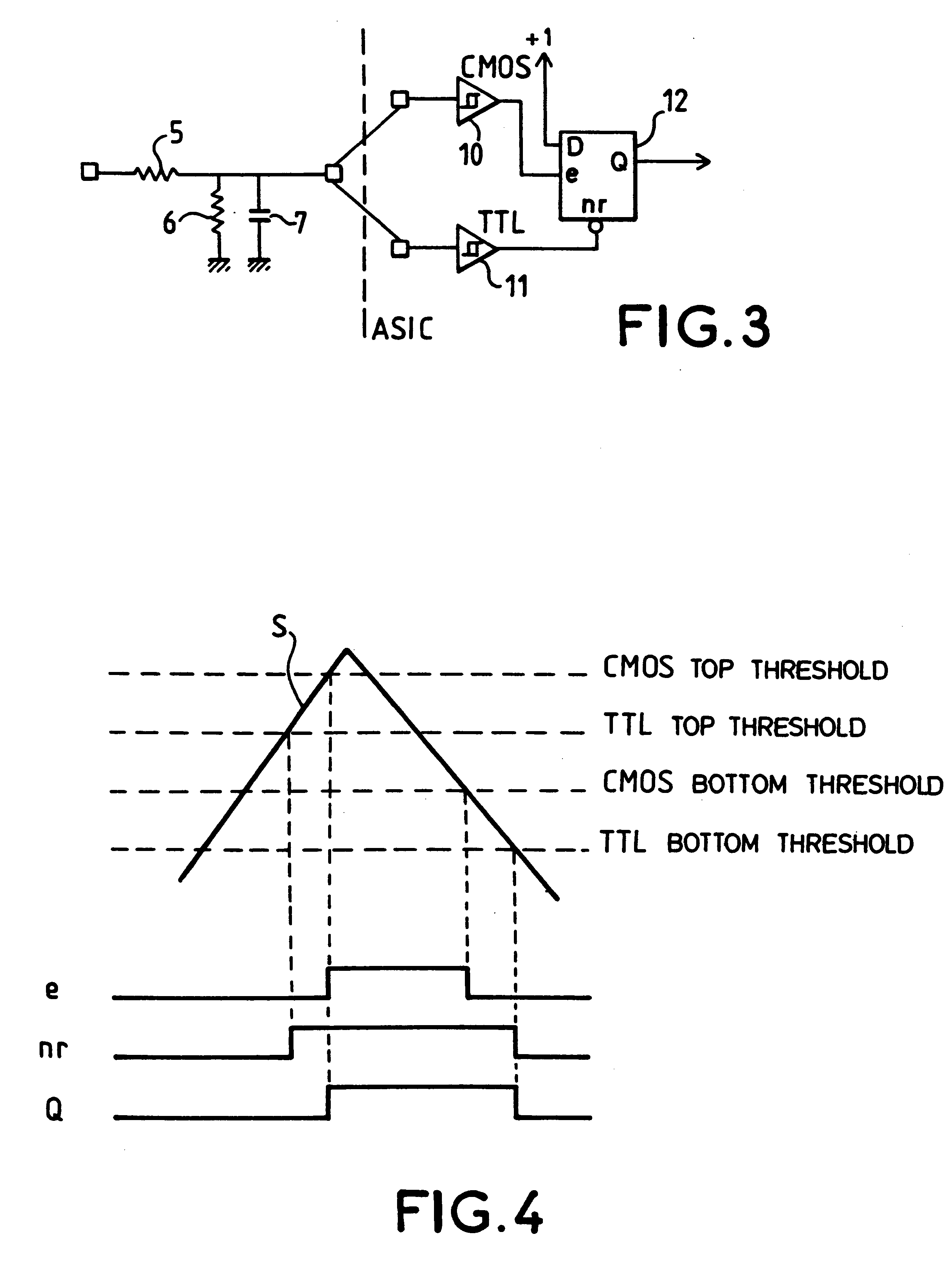
The discrete-rendering logic circuit, by enabling the selection of one of the input Schmitt triggers for the upward crossing of its top threshold and the other Schmitt trigger for the downward crossing of its bottom threshold while at the same time, when necessary, ensuring the sensitivity of these two Schmitt triggers to the crossings of these two thresholds, more than doubles the freedom of choice of the designer of ASIC digital integrated circuits, and this freedom of choice is all the greater as the number of types of input Schmitt triggers is great.
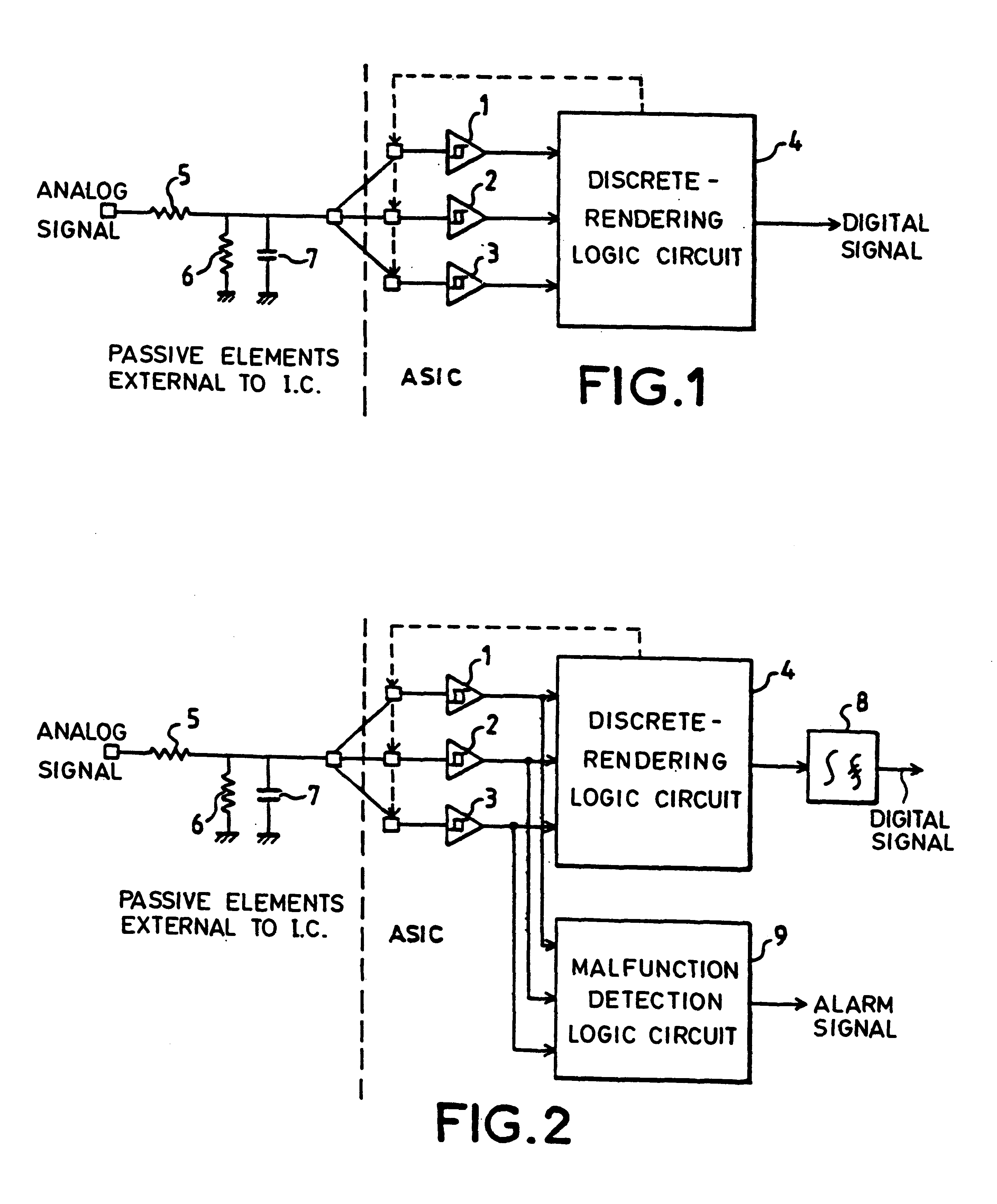
Advantageously, the circuit for the acquisition of a binary analog signal, in addition to the Schmitt triggers with different switching thresholds, parallel-connected by their inputs and in addition to the discrete-rendering logic circuit, connected to the outputs of the Schmitt triggers, which deduces the state of the binary analog signal from the combination of the output states of the Schmitt triggers, comprises an output digital filter eliminating the transient noises caused by the asynchronous operation of the different Schmitt triggers.

Problems solved by technology

Consequently, it has the drawback wherein its electrical characteristics, hence its switching thresholds, are fixed during the characterizing of its integration cell.
It sometimes happens that, in the set of Schmitt trigger input digital stages available, none is really suitable.
The result of this is that, unless the costly solution of developing a specific cell is adopted, the designer of an ASIC circuit must opt for an available type of Schmitt trigger digital input stage having top and bottom switching thresholds which are not at the desired levels but are simply close to them.

Method used


Image

  • Circuit for the acquisition of binary analog signals
  • Circuit for the acquisition of binary analog signals
  • Circuit for the acquisition of binary analog signals

Examples


Embodiment Construction

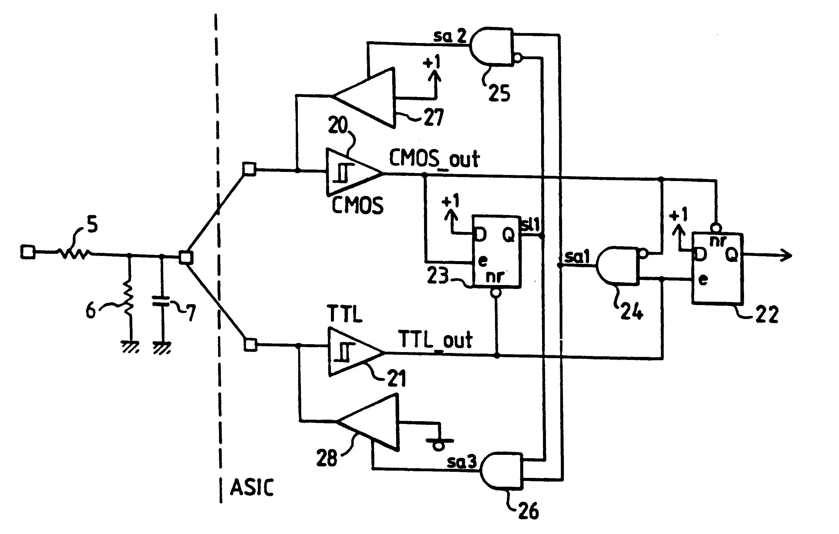
The circuit for the acquisition of a binary analog signal that is going to be described is integrated into the chip of an ASIC digital circuit. It is shown in FIG. 1, behind a purely passive analog stage, external to the chip of the ASIC digital integrated circuit, matching the range of variation of voltage of the binary analog signal with the range of variation of voltage accepted by the ASIC digital integrated circuit. It essentially has one input stage formed by a bank of Schmitt triggers 1, 2, 3 of different types whose inputs are parallel-connected and one output stage constituted by a discrete-rendering logic circuit 4 deducing the state of the binary analog signal from the combination of the output states of the bank of input Schmitt triggers 1, 2, 3 and acting, as the case may be, on the input signal (feedback connection shown in dashes) to sensitize the Schmitt triggers.

The input passive analog stage, which is external to the ASIC digital integrated circuit, is constituted ...


PUM


Abstract

The disclosure relates to the acquisition of a binary analog signal at input of a digital integrated circuit after its range of voltage variation has been matched with that acceptable by the digital integrated circuit by means of a resistive divider bridge. It is usual to define the architecture of an ASIC digital integrated circuit on the basis of libraries of pre-characterized cells. The disclosed device is designed to increase the possibilities of choice open to the integrated circuit designer, in enabling him to one pre-characterized cell of a Schmitt trigger for its top switching threshold and another for its bottom switching threshold. It consists of a circuit comprising, at input, a bank of Schmitt triggers of different types, followed by a discrete-rendering logic circuit deducing the logic state of the binary input analog signal of the combination of the output states of the input Schmitt triggers.

Description

1. Field of the InventionThe present invention relates to the acquisition of binary analog signals at input of a digital integrated circuit.The dialog between the computer and its peripherals or between several computers or again between a human operator and a computer is often carried out by means of discrete or Boolean analog electrical signals evolving around two voltage thresholds which are at a variable distance from each other, depending on the tolerated noise margins. The voltages then brought into play may be great as compared with the usually accepted voltages in the digital integration technologies most commonly used today (voltages of 5 V), thus making it necessary to obtain a voltage matching. This matching conventionally makes use of an analog interface stage with a resistive divider bridge possibly incorporating a filtering capacitor. When the voltage matching is done, it is necessary to determine the binary state of the signal by comparing its instantaneous voltage wi...

Claims


Application Information

Patent Timeline
Patent Type & Authority Patents(United States)
IPC IPC(8): H03K5/1252H03K5/08H03K5/125H03K3/037
CPCG11C27/024H03K3/0377H03K5/08H03K5/1252
Inventor BIETH, PHILIPPEPITOT, CHRISTIANPROST, MICHEL
Owner SEXTANT AVIONIQUE
Learn More