Zero force heat sink

a heat sink and zero force technology, applied in the direction of cooling/ventilation/heating modification, semiconductor/solid-state device details, semiconductor devices, etc., can solve the problems of reducing the reliability of the final system design, reducing the range of allowable power dissipation of electronic packages, and adding undesirable costs and complexity

Inactive Publication Date: 2001-04-03
IBM CORP
View PDF7 Cites 106 Cited by
  • Summary
  • Abstract
  • Description
  • Claims
  • Application Information

AI Technical Summary

Problems solved by technology

Current industry solutions have included the use of active heat sinks or elaborate structures to improve the thermal load carrying capacity of select components; however, these approaches tend to add undesirable cost and complexity, and also reduce reliability of the final system design.
A simple solution appears to be the use of larger and heavier heat sinks since limitations in heat sink mass limit the range of allowable electronic package power dissipation.
However, larger and heavier heat sinks have not proven effective, particularly when they are applied to surface mounted components.
There are serious constraints linked to the amount of heat sink mass which can actually be supported without adversely affecting the reliability of the interconnections to surface mounted components.
Large mass heat sinks cause excessive stresses to both first and second level interconnections (i.e., component to heat sink being the site of firs

Method used


Image

  • Zero force heat sink
  • Zero force heat sink
  • Zero force heat sink

Examples


Embodiment Construction

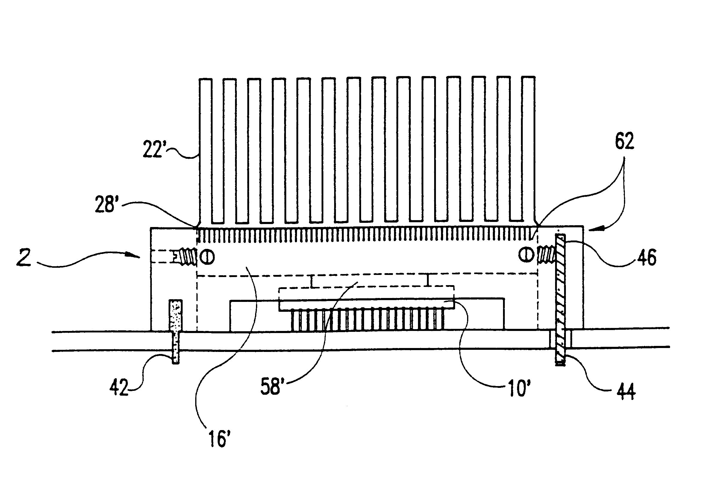
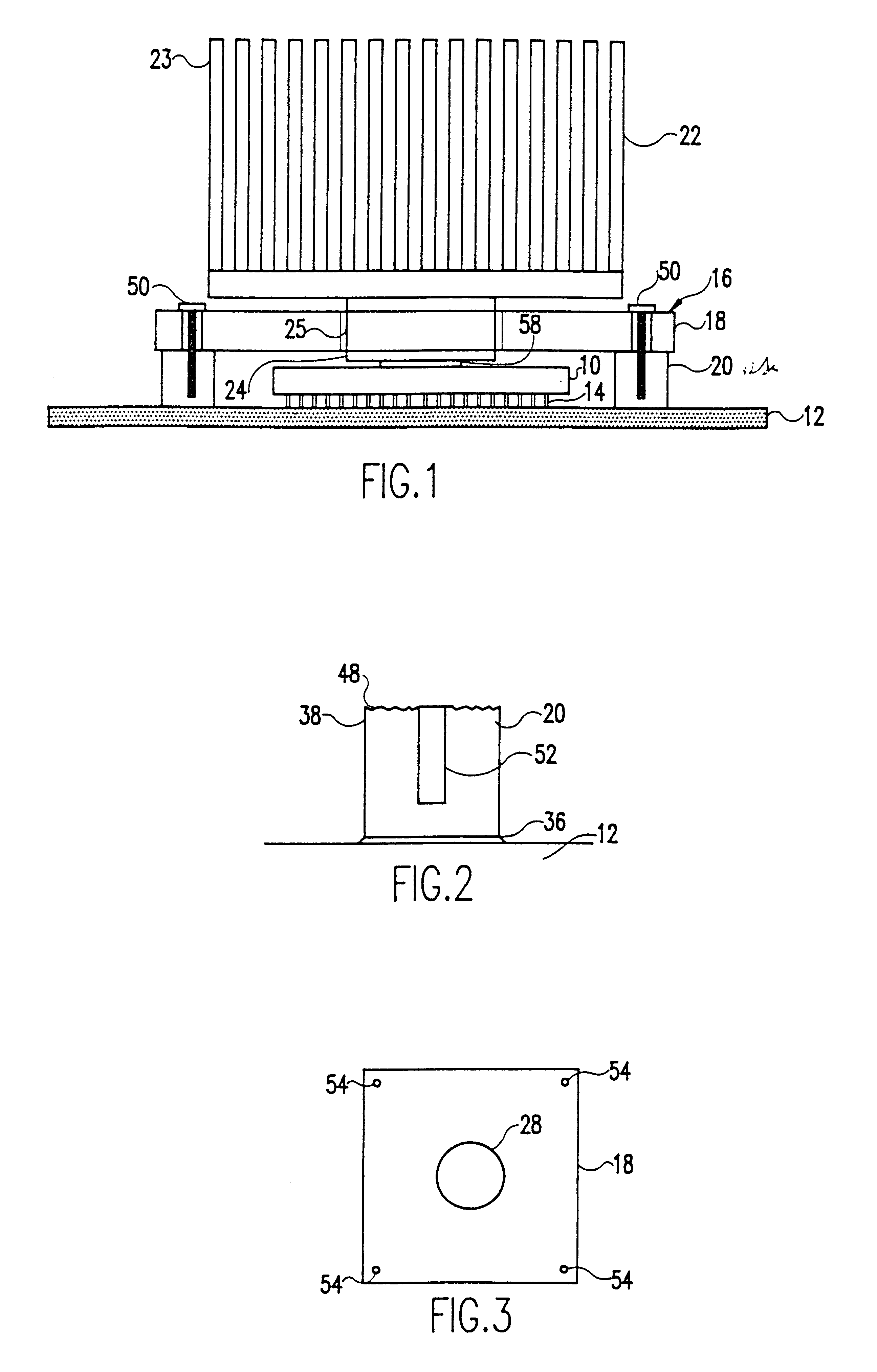
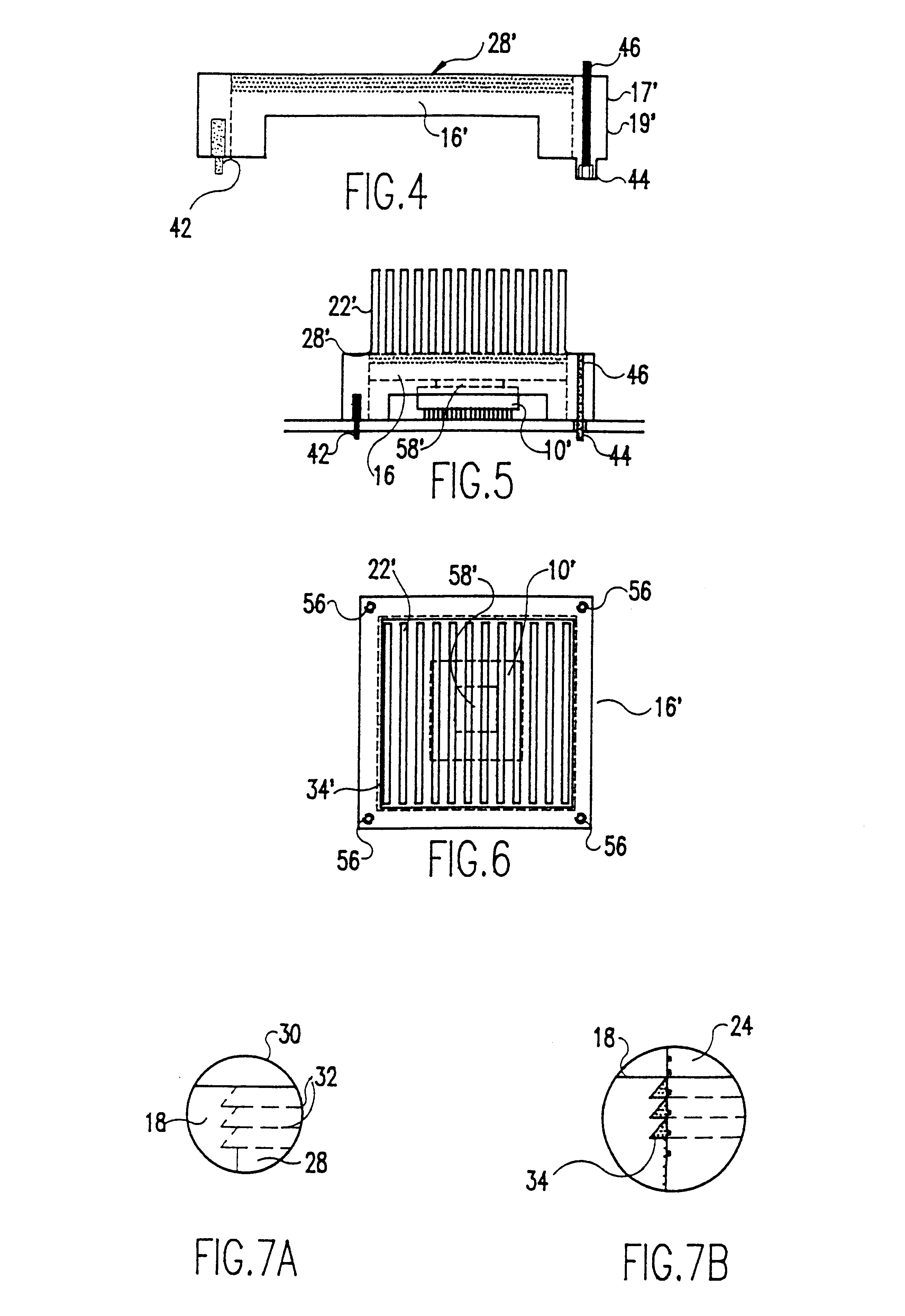
This invention pertains to decoupling those forces generated by a heat sink mass from an underlying substrate, and particularly a surface mounted substrate. Decoupling a force due to the heat sink mass from the electronic package and its interconnection structure enables and simplifies the use of larger and heavier heat sinks. The use of high mass heat sinks enables higher power dissipations for a given electronic package type. According to this invention, decoupling is accomplished by using a rigid frame to support the weight of the heat sink while maintaining the heat sink in thermal contact with the electronic package. When subjected to vibration and / or shocks during transportation or operation, the frame restrains and limits the displacement of the heat sink relative to the electronic package. Additionally, the frame transfers static and dynamic loading from the heat sink directly to the underlying printed circuit board or card.

FIG. 1 shows a substrate 10 positioned on a support...


PUM


Abstract

A heat sink in a heat transfer relationship with a substrate such as an integrated chip, chip carrier, or other electronic package. The heat sink is connected to a frame which is connected to a printed circuit board or other suitable support on which the substrate is positioned. The heat sink, which extends through an aperture in the frame is coupled to a surface of the substrate. The heat sink is mechanically decoupled from the substrate. Large heat sinks may be thermally connected to surface mount substrates mounted using technologies such as ceramic ball or column grid arrays, plastic ball or column grid arrays, or solder balls or columns. The heat sink is attached coaxially through the aperture to the substrate. After assembly and lead/tin or other metallic surface mount interconnects are relaxed such that the substrate and is completely supported by the frame and the heat sink imparts zero or nearly zero downward force. Because the heat sink moves freely within the aperture during assembly, the heat sink package is useful for a variety of different substrates. Preferably, the frame is a plate and a plurality of studs. The plate material are selected to match the thermal expansion of the underlying support, and the stud material matched the thermal expansion of the substrate. Thus, the frame construction allows matching expansion and contraction of the assembly to the underlying substrate and support.

Description

1. Field of the InventionThe present invention generally relates to heat sink assemblies and, more particularly, to a technique and assembly arrangement wherein a heat sink is positioned in thermal contact with a substrate such as an integrated circuit chip or electronic package but does not impart any stressful forces on the substrate, thereby avoiding damage to interconnect both at the heat sink substrate interface and at the substrate underlying support interface.2. Background DescriptionModern integrated circuit chips, chip carriers, and other electronic substrates and the use of higher powers in these devices mandate a need for better heat dissipation schemes. Current industry solutions have included the use of active heat sinks or elaborate structures to improve the thermal load carrying capacity of select components; however, these approaches tend to add undesirable cost and complexity, and also reduce reliability of the final system design.A simple solution appears to be the...

Claims


Application Information

Patent Timeline
IPC IPC(8): H01L23/34H01L23/40
CPCH01L23/4006H01L2224/16225H01L2924/09701
Inventor ATWOOD, EUGENE R.BENENATI, JOSEPH A.DANKELMAN, JAMES J.QUINONES, HORATIOPUTTLITZ, KARL J.KASTBERG, ERIC J.
Owner IBM CORP
Why Eureka
Try Eureka