Friction clutch with nickel-chromium alloy spring elements

a technology of friction clutches and spring elements, applied in the field of friction clutches, can solve the problems of increasing the inertial mass, losing elastic properties and strength, and even irreversible loss

a technology of friction clutches and spring elements, applied in the field of friction clutches, can solve the problems of increasing the inertial mass, losing elastic properties and strength, and even irreversible loss

US6216839B1Inactive Publication Date: 2001-04-17SACHS RACE ENG

Image

  • Friction clutch with nickel-chromium alloy spring elements
  • Friction clutch with nickel-chromium alloy spring elements
  • Friction clutch with nickel-chromium alloy spring elements

Examples


Embodiment Construction

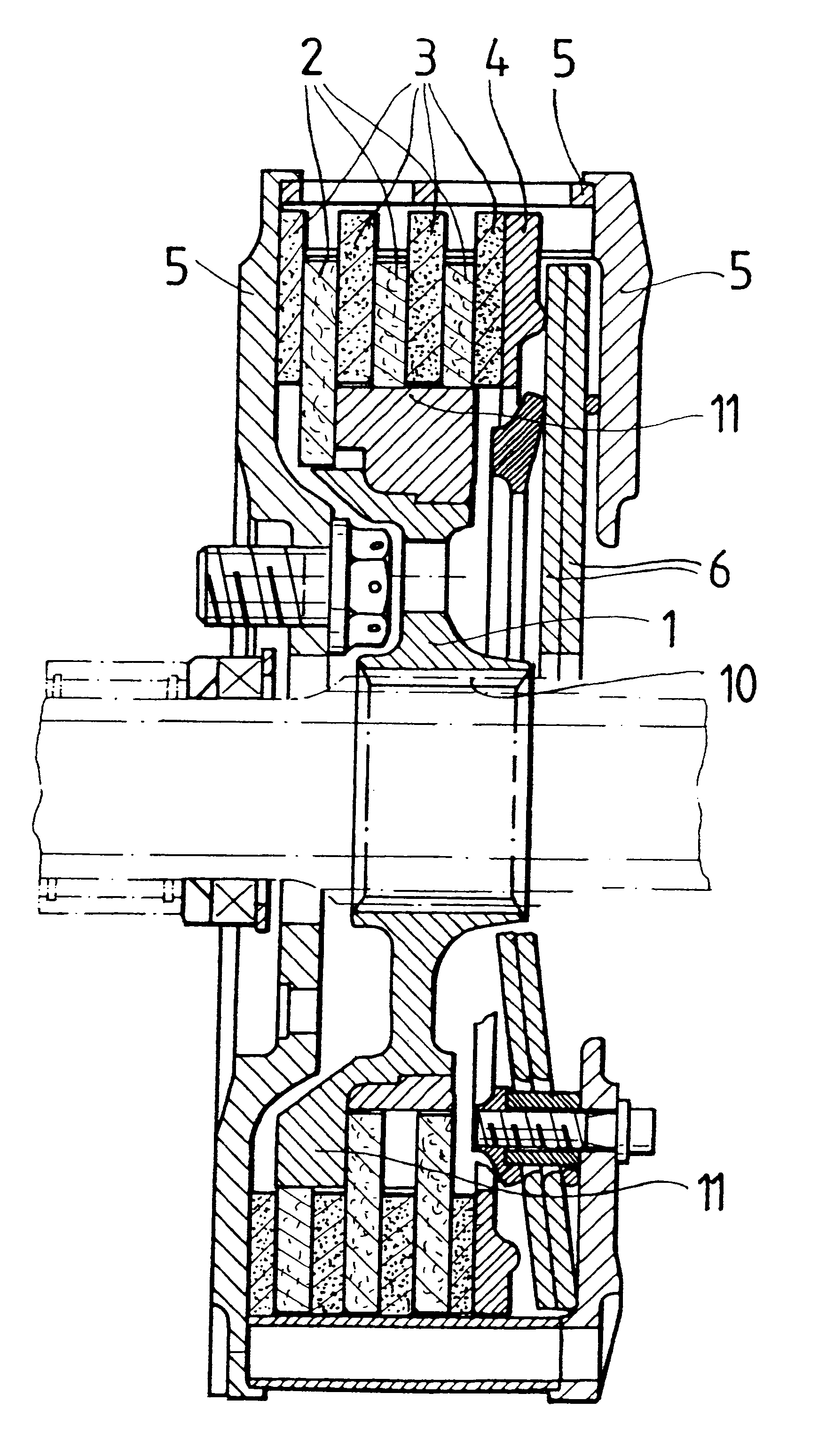
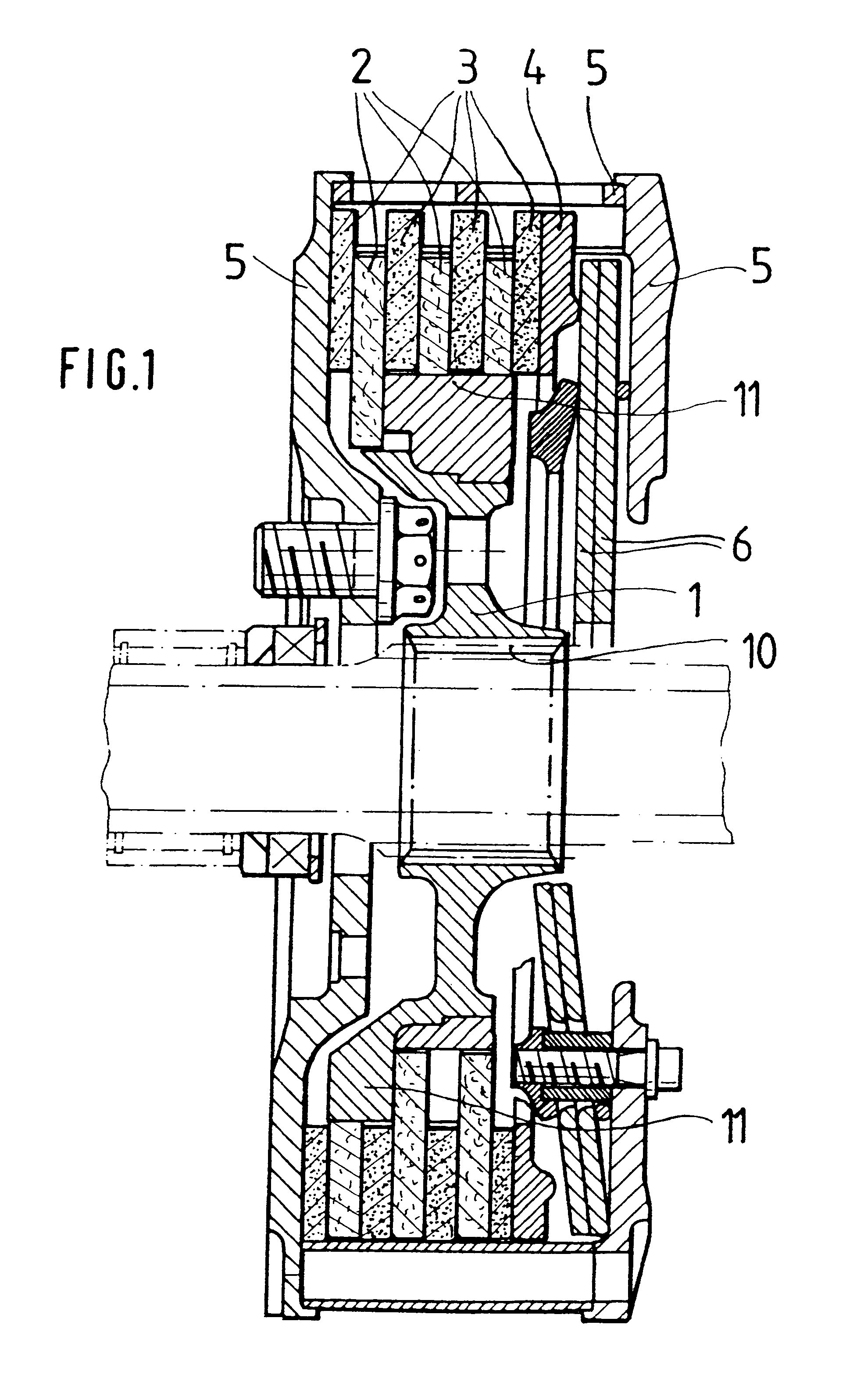
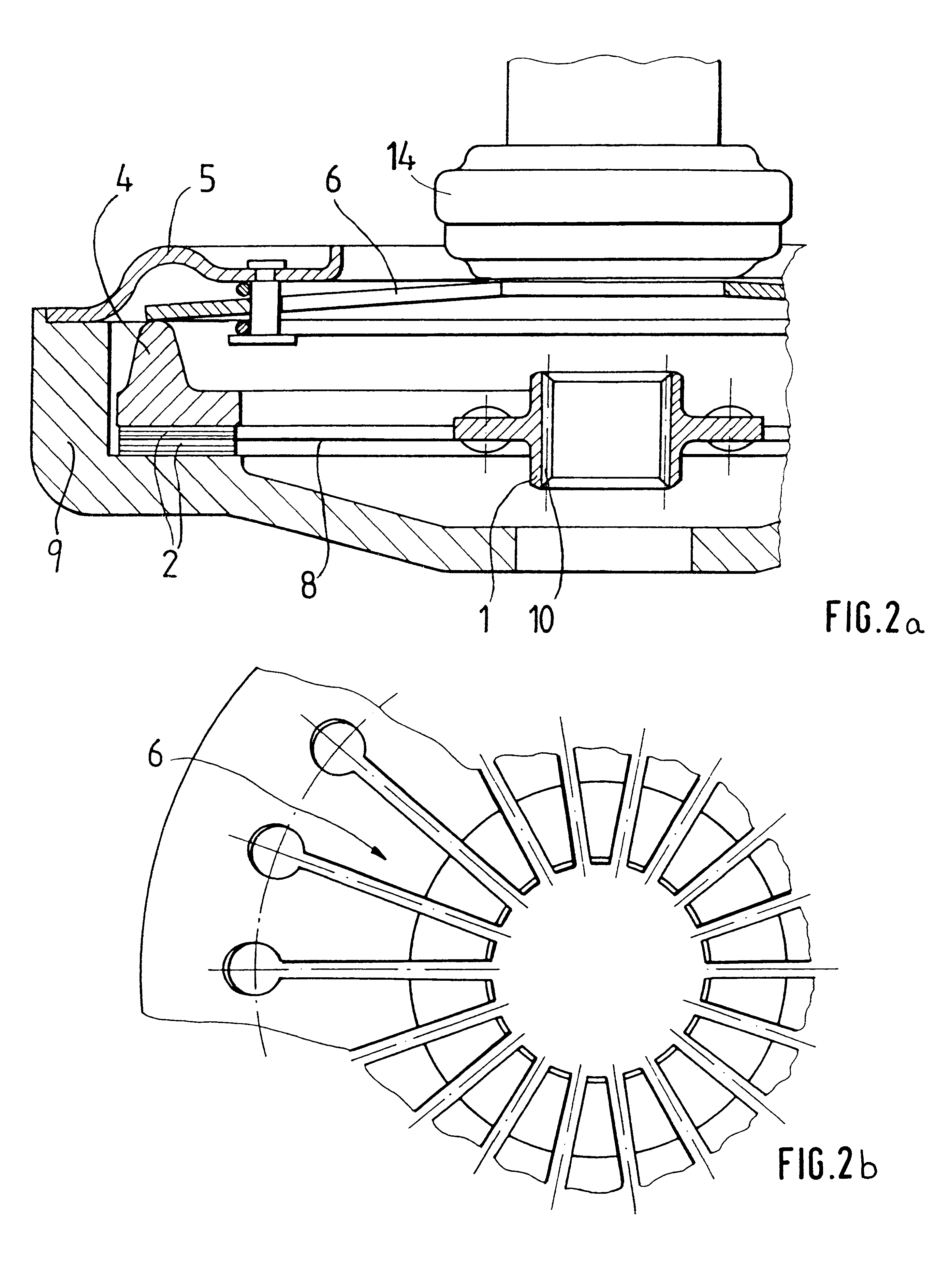
The multidisk clutch shown in FIG. 1 has a hub 1 with internal toothing 10 in order for it to be mounted in a rotationally fixed, axially displaceable manner on a transmission shaft. Via further external toothing 11, the friction linings 2 are connected to the hub 10 in a rotationally fixed manner. A further set of friction linings 3 is connected, in a rotationally fixed manner, to the three-part clutch casing 5. As can be seen from the drawing, the friction linings 2 and the friction linings 3 are arranged alternately in the axial direction, so that when the casing 5 rotates with respect to the hub 1 the friction linings 2 and 3 are able to transmit a dragging moment. The friction between the linings 2 and 3 is determined, inter alia, by the pressure force of the spring device 6, which in this case is designed as a diaphragm spring and acts on the pressure plate 4, which is guided in a rotationally fixed manner in the clutch casing 5. The spring device 6 is in this case supported i...


PUM

PropertyMeasurementUnit
Fractionaaaaaaaaaa
Fractionaaaaaaaaaa
Fractionaaaaaaaaaa

Abstract

A friction coupling for use in particular in the drive train of a motor vehicle includes a clutch casing, a pressure plate which is guided in a rotationally fixed manner with respect to the clutch casing, at least one clutch disk and a spring device containing about 40-60% nickel. A method for coating a nickel-base material, in particular the above mentioned spring element for friction clutches, wherein at least part of the surface of the spring device contains boride, and also a method for producing such a spring device which includes a heat treatment are also disclosed.

Description

1. Field of the InventionThe present invention relates to friction clutches, in particular for motor vehicles with internal combustion engines, including a clutch casing, a pressure plate which is guided in a rotationally fixed manner with respect to the clutch casing, at least one clutch disk and a spring device comprising from about 40 to 65% nickel.2. Background of the InventionInternal combustion engines provide a torque which can be used for drive purposes only within the speed range between idling speed and nominal speed. Motor vehicles therefore generally require a transmission and a device for separating the engine from the drive train. In the case of manual transmissions, a friction clutch is typically used for this purpose, and this clutch also allows an initially stationary vehicle to be driven off. Friction clutches of the prior art comprise a clutch casing, in which a pressure plate is guided in a rotationally fixed manner and is acted on by spring elements, and at leas...

Claims


Application Information

Patent Timeline
17 Apr 2001
Publication
US6216839B1
IPC
F16D13/58; F16D13/71; C22C19/03; C22C19/05
CPC
F16D13/583; F16D2013/706
Inventors
RUDOLF, THOMAS; BETTEN, KLAUS