Method for rapid forming of a ceramic work piece

a technology of ceramic workpieces and forming methods, applied in the direction of additive manufacturing processes, manufacturing tools, electric/magnetic/electromagnetic heating, etc., can solve the problems of ceramic workpiece cracking, long processing time, and short amount of time required for each laser ceramic sintering cycle involving both heating and cooling

Inactive Publication Date: 2001-04-17
NAT SCI COUNCIL
View PDF3 Cites 190 Cited by
  • Summary
  • Abstract
  • Description
  • Claims
  • Application Information

AI Technical Summary

Problems solved by technology

While the above-mentioned indirect process of ceramic making can make workpieces of complex configurations and can save the usage of molds and dies, there are drawbacks such as: requiring further sintering steps, which demands both additional equipment and technical know-how; requiring further removal of the binding agents during the conventional sintering, which prolonges the processing time since the entire ceramic making process can not be completed in consecutive steps.
However, the amount of time required for each laser ceramic sintering cycle involving both heating and cooling can be as short as one second.
Unless the overall thickness of the ceramic workpiece being sintered by a high energy beam is extremely thin, the ceramic workpiece will tend to crack due to internal stress caused by thermal shock.
However, the water content of the plastic green mixture can not be too low as to obstruct the mixture from forming a thin green layer conveniently.
A green body block with Al(H.sub.2 (PO.sub.4)).sub.3 as a binder can also be removed by soaking in a water bath, but areas within 1 mm vicinity of the sintered ceramic portion have undergone an irreversible chemical reaction induced by high temperature such that this part of green portion can not be removed effectively by soaking in water.

Method used


Image

  • Method for rapid forming of a ceramic work piece
  • Method for rapid forming of a ceramic work piece
  • Method for rapid forming of a ceramic work piece

Examples


process embodiment

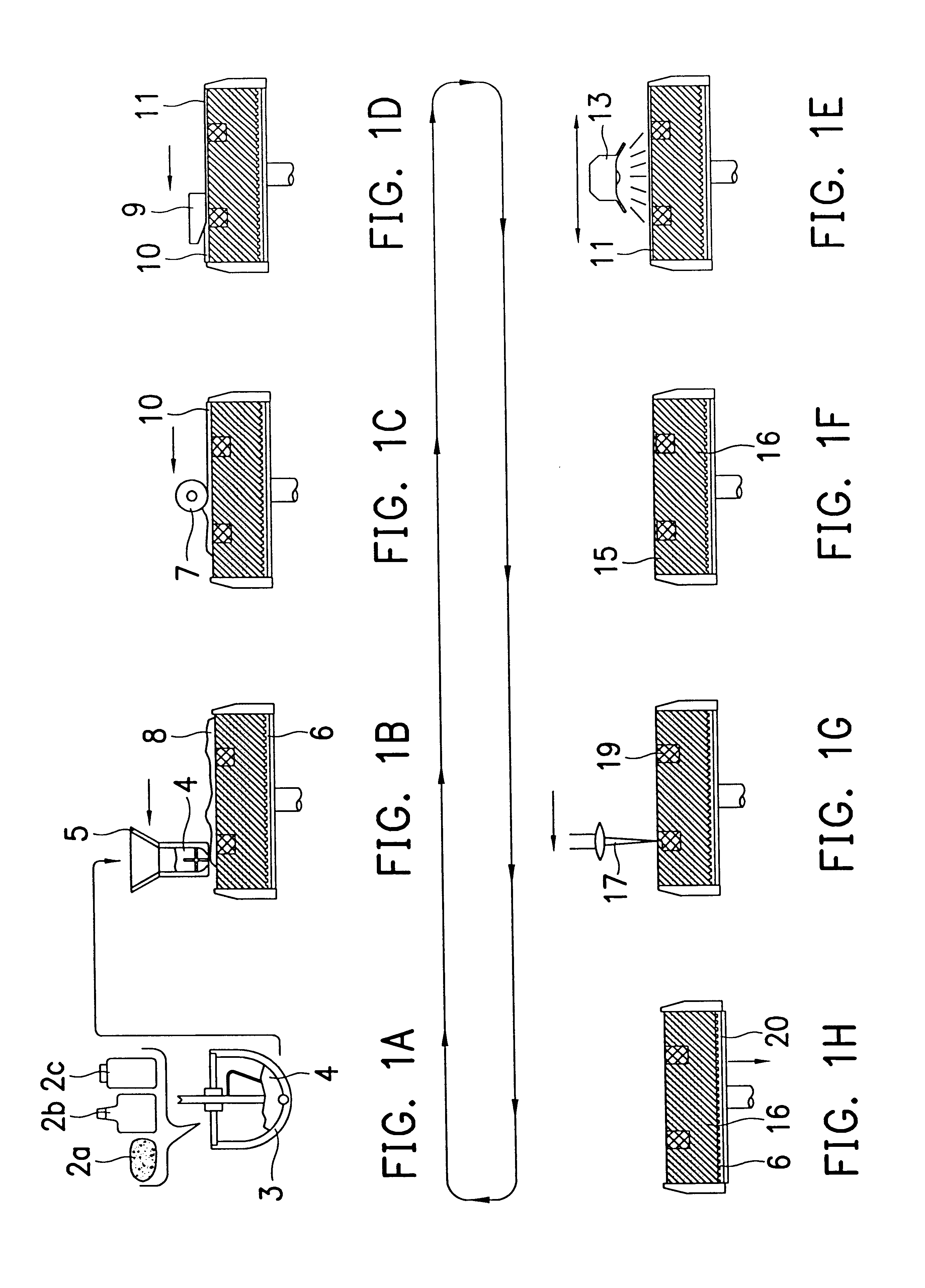
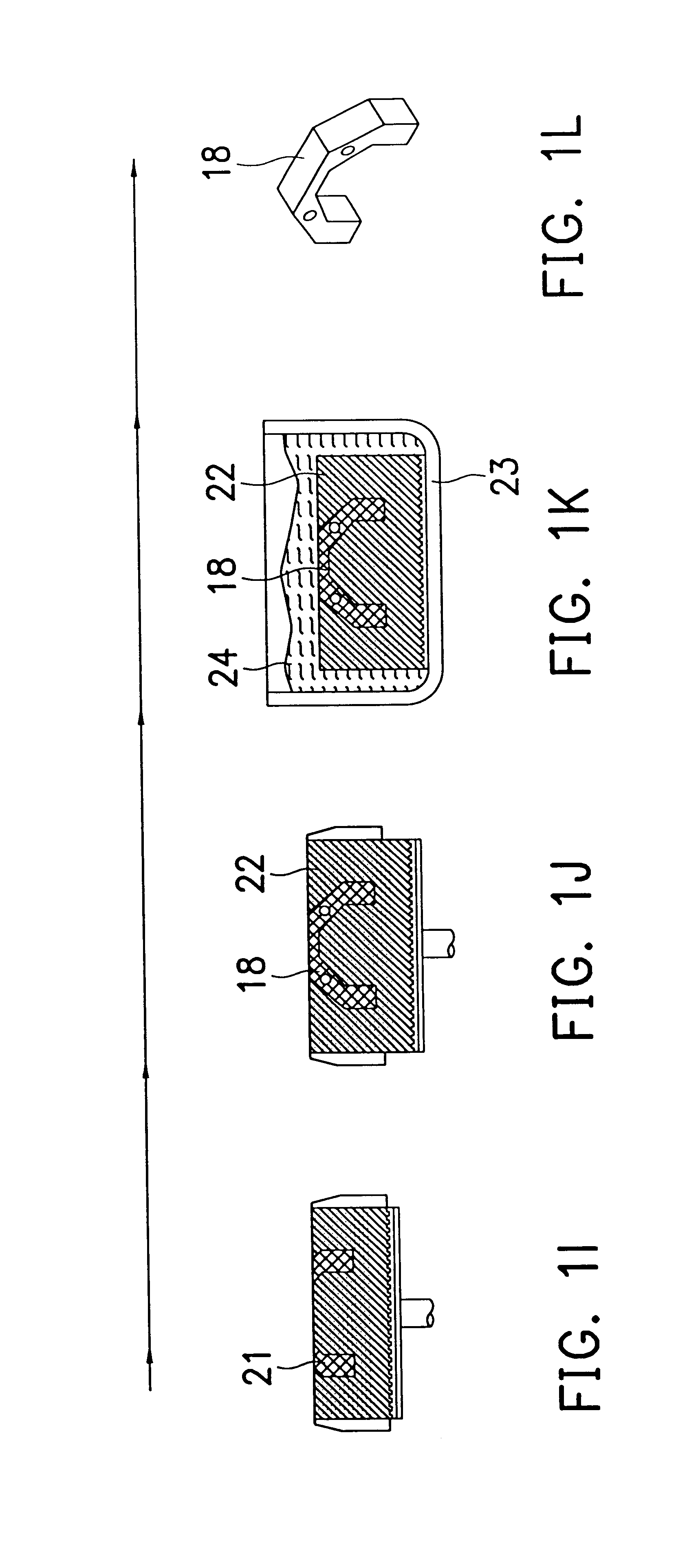
The above has described technologies and equipment's related to each step of the ceramic fabricating process according to the present invention. For further understanding of the present invention, a more detailed description of the method embodiment for rapid ceramic workpiece fabrication according to the present invention is herein provided with the illustrations of FIG. 1A to FIG. 1L.

FIG. 1A, which is equivalent to Step (a), shows the step to prepare the plastic green mixture starting with composing material. The ceramic powder 2a, inorganic binder 2b, and dissolving agent 2c are all placed inside a mixing device 3 with suitable proportions to be mixed thoroughly, then the mixed composition materials, plastic green mixture 4, are unloaded to the feeding container 5.

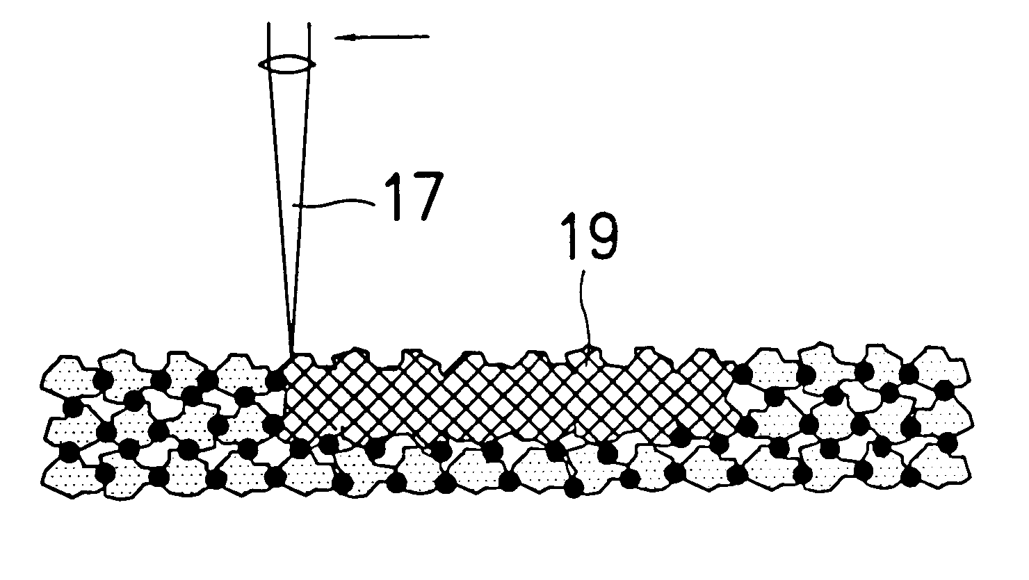
FIG. 1B to FIG. 1F illustrate the steps for forming a thin layer of the plastic green mixture as described in Step (b). A feeding device feeds the plastic green mixture 4 onto the top surface of the worktable 6 as shown...


PUM

PropertyMeasurementUnit
particle sizeaaaaaaaaaa
temperatureaaaaaaaaaa
water contentaaaaaaaaaa

Abstract

An inorganic binder and a dissolving agent are put into ceramic powder. They are mixed to form a plastic green mixture. Then the said mixture is formed into a thin green layer. Preferably, this thin green layer will be preheated and dried such that the thin green layer will be hardened due to the bonding effect of the inorganic binder. A portion of the thin green layer exposed under a directed high-energy beam is sintered, preferably by a laser beam, to cause ceramic molecules to bond together locally due to heat fusion. By controlling the scanning path of the high-energy beam, a two-dimensional thin cross section of the ceramic part in arbitrary form can be produced. A second thin ceramic layer can be built onto the first thin ceramic layer and bonded to it by the same method. After multiple repetitions of this procedure a three dimensional ceramic part can be fabricated layer upon layer. The green portion, which is not scanned by the high-energy beam, will be removed with suitable method. A ceramic part can be rapidly produced in this way.

Description

1. Field of the InventionThe present invention relates to apparatus and method for direct and rapid forming of a ceramic work piece; more specifically, the present invention provides an apparatus and a method for directly, rapidly, and precisely fabricating a three-dimensional (3-D) ceramic work piece by a high energy beam, skipping the conventional process of sintering a ceramic workpiece in a furnace.2. Description of Related ArtIn the past decades, rapid prototyping combining the latest computer, manufacturing, and material science technology has provided a number of fabricating methods for producing three-dimensional, or 3-D, workpieces directly and rapidly. These fabricating methods vary in that some employ light energy to induce chemical bonding among involved materials, some employ heat fusion, and some employ adhesive to glue fragments of the workpiece together, etc. In terms of material used, metals, ceramics, polymers, and others are all possible candidates. Since differen...

Claims


Application Information

Patent Timeline
Patent Type & Authority Patents(United States)
IPC IPC(8): B29C67/00B28B11/00B28B13/00B28B11/24B28B13/02B28B1/00C04B35/622C04B35/111C04B40/00
CPCB28B1/00B28B1/001B28B11/243B28B13/0215B29C67/0077B29C67/0081C04B35/111C04B35/622C04B40/0092B29C64/153B29C64/165B33Y10/00B33Y70/00
Inventor TANG, HWAHSING
Owner NAT SCI COUNCIL
Why Eureka
Try Eureka