On-line dynamic corrections adjustment method

a dynamic correction and adjustment method technology, applied in the direction of discharge tube/lamp details, instruments, heat measurement, etc., can solve the problems of inability to extend the knife-edge resolution evaluation technique to e-beam projection systems having a large beam, inability to adjust, and inability to achieve the effect of large beam,

Inactive Publication Date: 2001-04-17
NIKON CORP
View PDF6 Cites 36 Cited by
  • Summary
  • Abstract
  • Description
  • Claims
  • Application Information

AI Technical Summary

Problems solved by technology

Therefore, the adjustment procedure may be protracted and expensive.
However, the knife-edge resolution evaluation technique cannot be extended to e-beam projection systems having a large beam.
Such accuracy would be extremely expe

Method used


Image

  • On-line dynamic corrections adjustment method
  • On-line dynamic corrections adjustment method
  • On-line dynamic corrections adjustment method

Examples


Embodiment Construction

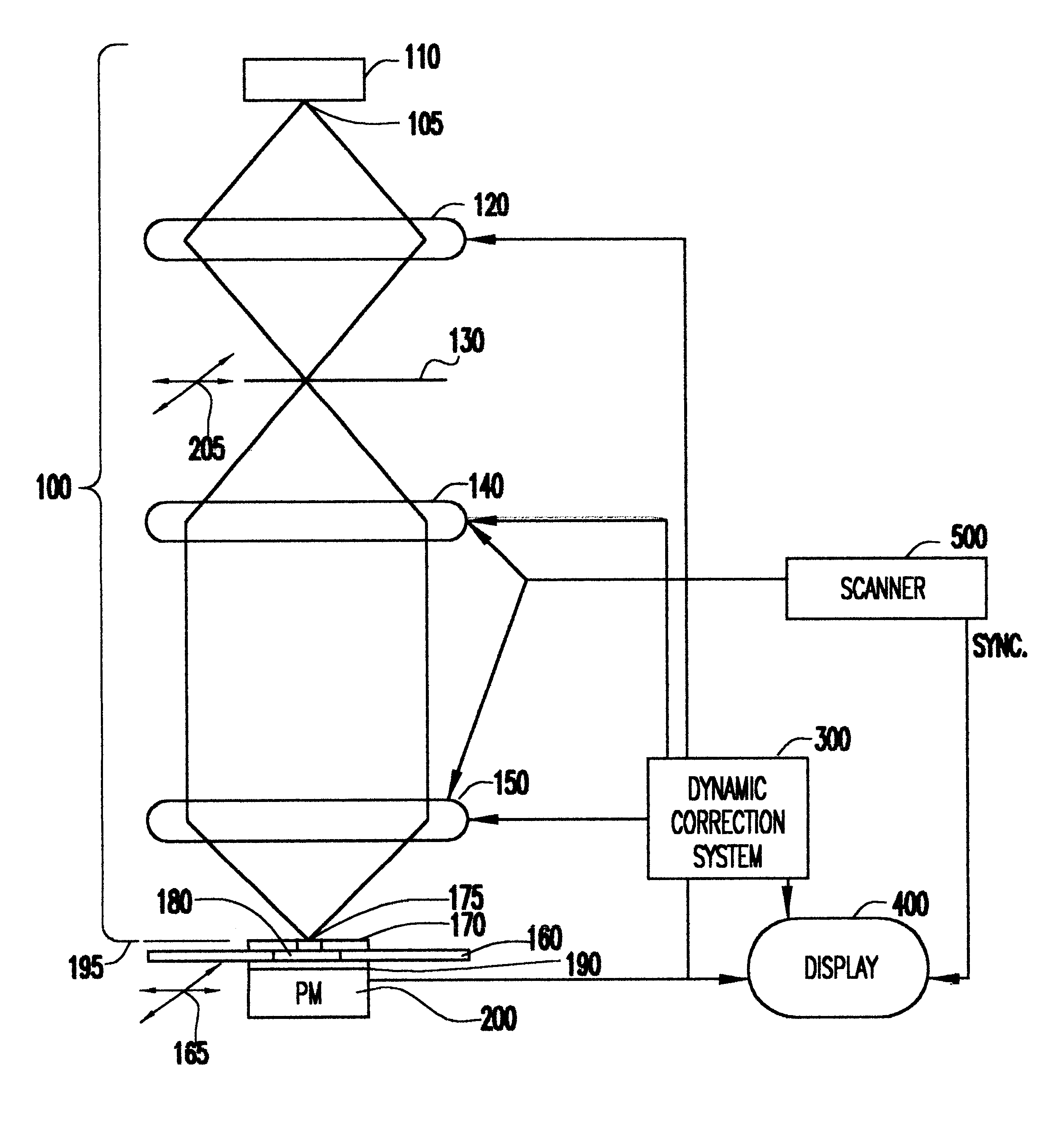
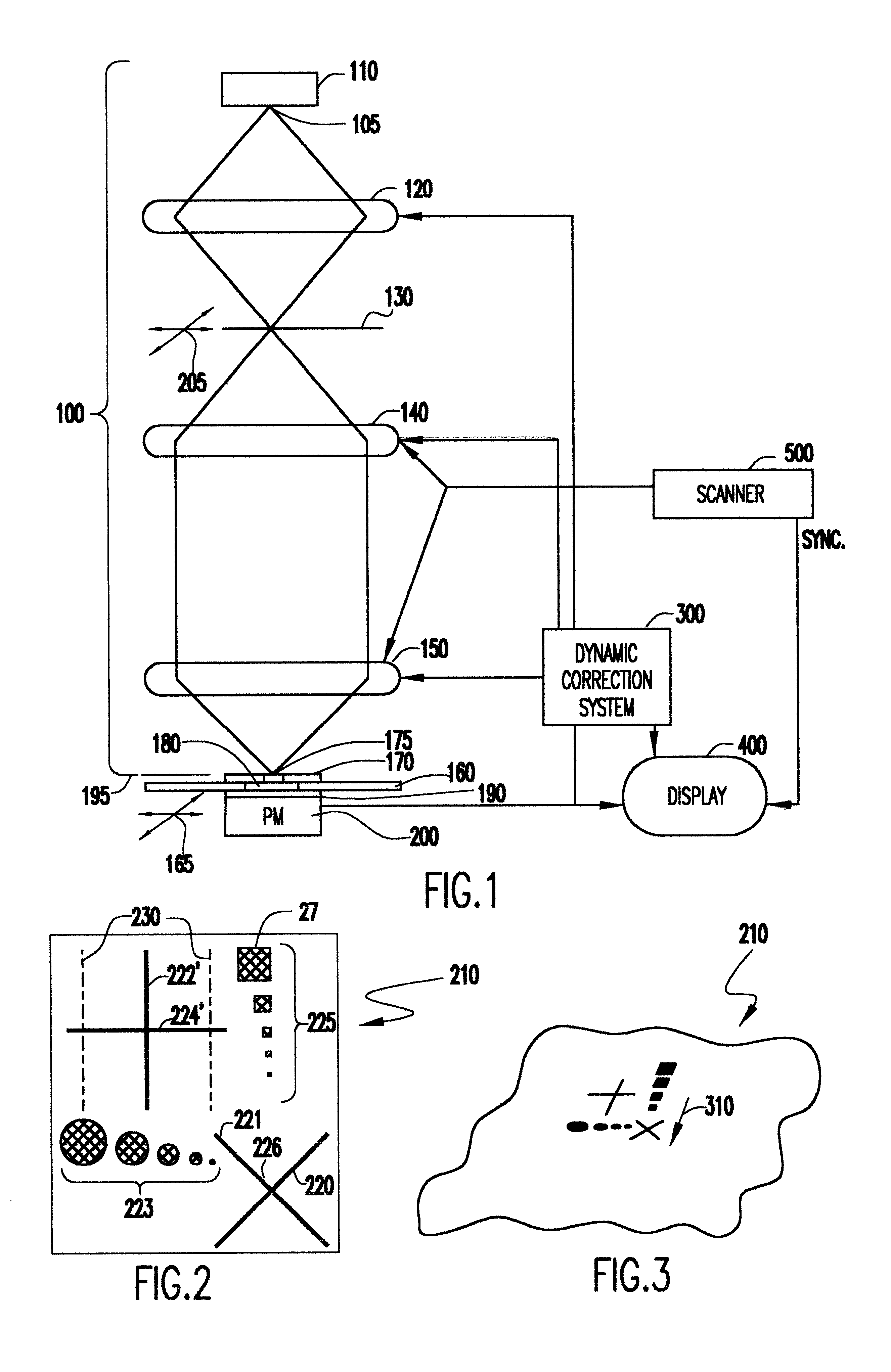
Referring now to the drawings, and more particularly to FIG. 1, there is shown, in generalized and schematic form a representative form of an e-beam projection system in combination with a schematic representation of the invention in combination therewith. It should be understood that the details of the form of the e-beam projection system, itself, is not particularly important to the practice of the invention and the illustration of FIG. 1 is provided to facilitate an understanding of the principles and operation of the invention.

By the same token, while the invention will be described in connection with the preferred application to e-beam projection lithography tools, the illustration of FIG. 1 should be considered as being generic to systems directed to other functionalities such as electron microscopy systems and systems using other species of charged particles such as ion beams. While some of the illustrated features of the e-beam projection column 100 (above the target plane 1...


PUM


Abstract

A small pinhole aperture and a scintillator are used to observe resolution in a charged particle beam system which is particularly applicable to electron beam projection devices in which the beam is several orders of magnitude larger than the desired resolution and minimum feature size to be produced. A pattern having a feature which is of comparable size to the desired resolution to be observed is scanned across the aperture in two dimensions and a synchronized display of measured light output from the scintillator allows real-time observation of the effects of correction adjustments on the resolution of the system. In this manner, a rough adjustment to near optimum corrections can be obtained over the deflection field in a much reduced number of iterations.

Description

1. Field of the InventionThe present invention generally relates to charged particle beam systems and, more particularly, to resolution measurement and adjustment in charged particle beam lithography and microscopy tools.2. Description of the Prior ArtNumerous techniques utilizing charged particle beams are known and in widespread use for manufacture of integrated circuit devices, in particular. For example, charged particle beams are used for implantation of impurities, inspection (e.g. with scanning electron microscopes) of structures for process evaluation and development and for lithographic patterning of substrates and layers deposited thereon. Essentially, lithography processes define potentially very minute areas and shapes on a surface through selective exposure and removal of portions of a layer of resist to expose areas of the surface for further processing by, for example, etching, implantation and / or deposition. For both lithographic patterning and inspection, electron b...

Claims


Application Information

Patent Timeline
IPC IPC(8): H01J37/244H01J37/304H01J37/30H01J37/147G03F7/20H01J37/305H01L21/027
CPCH01J37/244H01J37/304H01J2237/2823H01J2237/30433H01J2237/3175
Inventor GORDON, MICHAELGOLLADAY, STEVENROBINSON, CHRISROCKROHR, JAMES
Owner NIKON CORP
Why Eureka
Try Eureka