Coating composition for high temperature protection

a coating composition and high temperature protection technology, applied in the direction of superimposed coating process, coating, transportation and packaging, etc., can solve the problems of low toughness, undesirable phase structure of the coating and interdiffusion layer, and insufficient oxidation and corrosion protection of aluminum coatings, etc., to achieve the effect of improving the mechanical behavior

Inactive Publication Date: 2001-04-24
ANSALDO ENERGIA IP UK LTD
View PDF5 Cites 63 Cited by
  • Summary
  • Abstract
  • Description
  • Claims
  • Application Information

AI Technical Summary

Benefits of technology

It is an object of the present invention to provide an improved coating for structural parts of gas turbines which exhibits improved-mechanical behavior.
In an effort to develop a coating with improved mechanical properties--without sacrificing too much oxidation resistance--a variety of alloy compositions was evaluated. In order to prove the advantage of the preferred compositions of table 1 (b) a number of additional alloys whose compositions are given in Table 2 have also been tested. Compared with the preferred compositions, alloys EC0-EC6 were found to have either reduced oxidation resistance or inferior mechanical properties. Only the alloy according to the invention provides simultaneously high oxidation resistance and thermomechanical fatigue resistance and phase stability.

Problems solved by technology

Due to their limited thickness (typically around 50 .about..mu.m) aluminide coatings do not offer sufficient oxidation and corrosion protection for the long exposure times in stationary gas turbines (20000-50000 hours).
However, since a coated turbine blade undergoes complicated stress states during engine operation (especially during start up and shut down) advanced high temperature coatings must not only provide environmental protection but must also have specifically tailored physical and mechanical properties to provide high thermo-mechanical fatigue resistance.
However, the combination of Re with high Cr levels, typical for traditional coatings, results in an undesirable phase structure of the coating and interdiffusion layer.
This results in low toughness and low ductility.
However, the coatings are only intended for applications where the need for improved high temperature oxidation is paramount and where the coating ductility is relatively unimportant.

Method used


Image

  • Coating composition for high temperature protection
  • Coating composition for high temperature protection
  • Coating composition for high temperature protection

Examples


Embodiment Construction

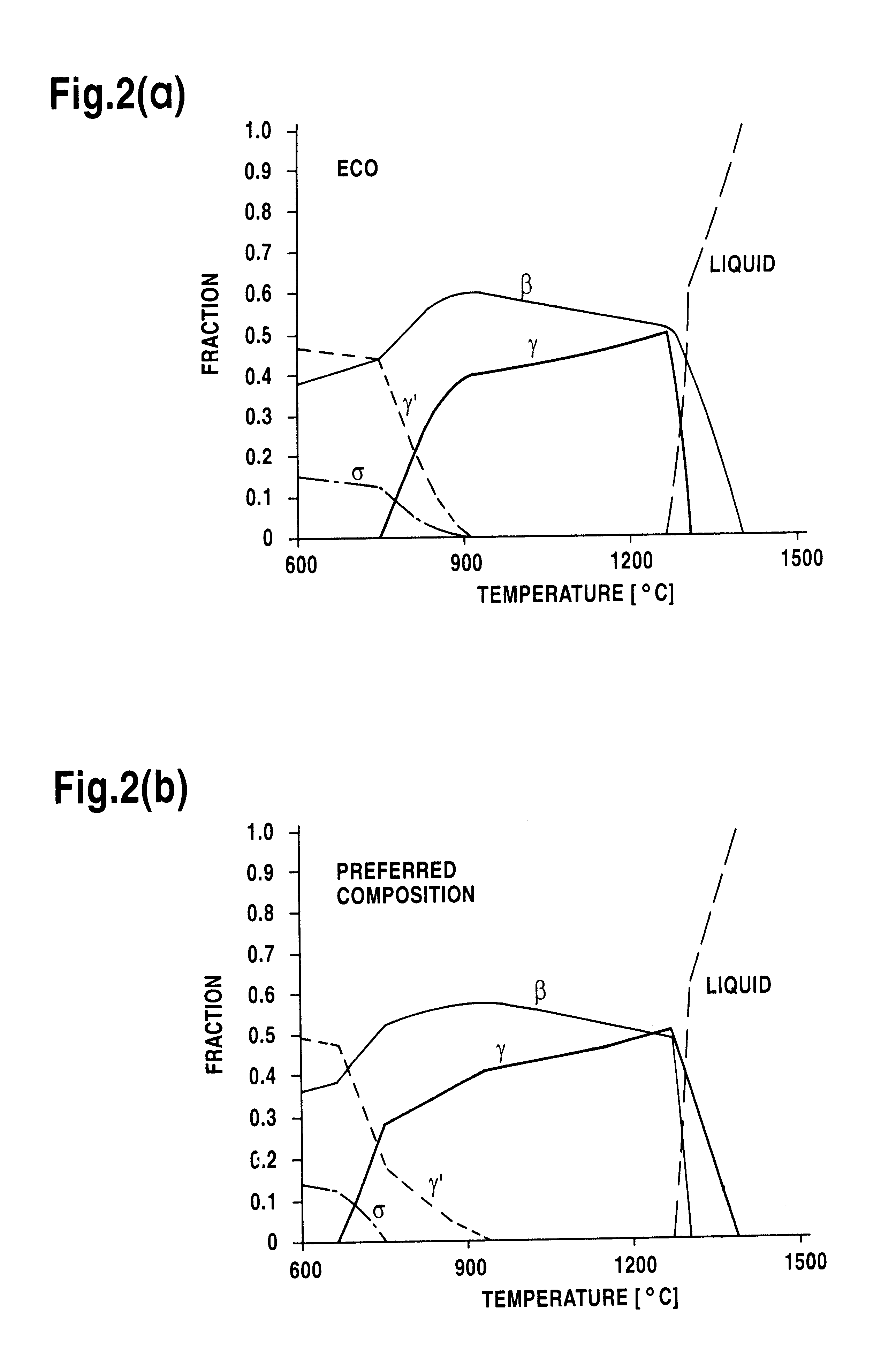
In the practice of the invention, coatings with compositions according to the present invention were produced by low pressure plasma spraying. A typical nickel base superalloy of the type used in gas turbine engines, known as CMSX4 (CMSX=trademark of Cannon Muskegan Co) and having a nominal composition of 9.5% Co, 6.5% Cr, 5.6% Al, 6.4% W, 6.5% Ta, 0.5% Mo, 1% Ti, 0.1% Hf, balance Ni was used as substrate for testing. The coating compositions which have been tested, are given in tables 1 (b) and 2. The performance of the coatings was evaluated by means of (i) isothermal oxidation at 1000 and 1050.degree. C. in a laboratory furnace, (ii) a water spray quench test and (iii) thermomechanical fatigue (TMF) testing at various upper temperature limits (800 to 1050.degree. C.).

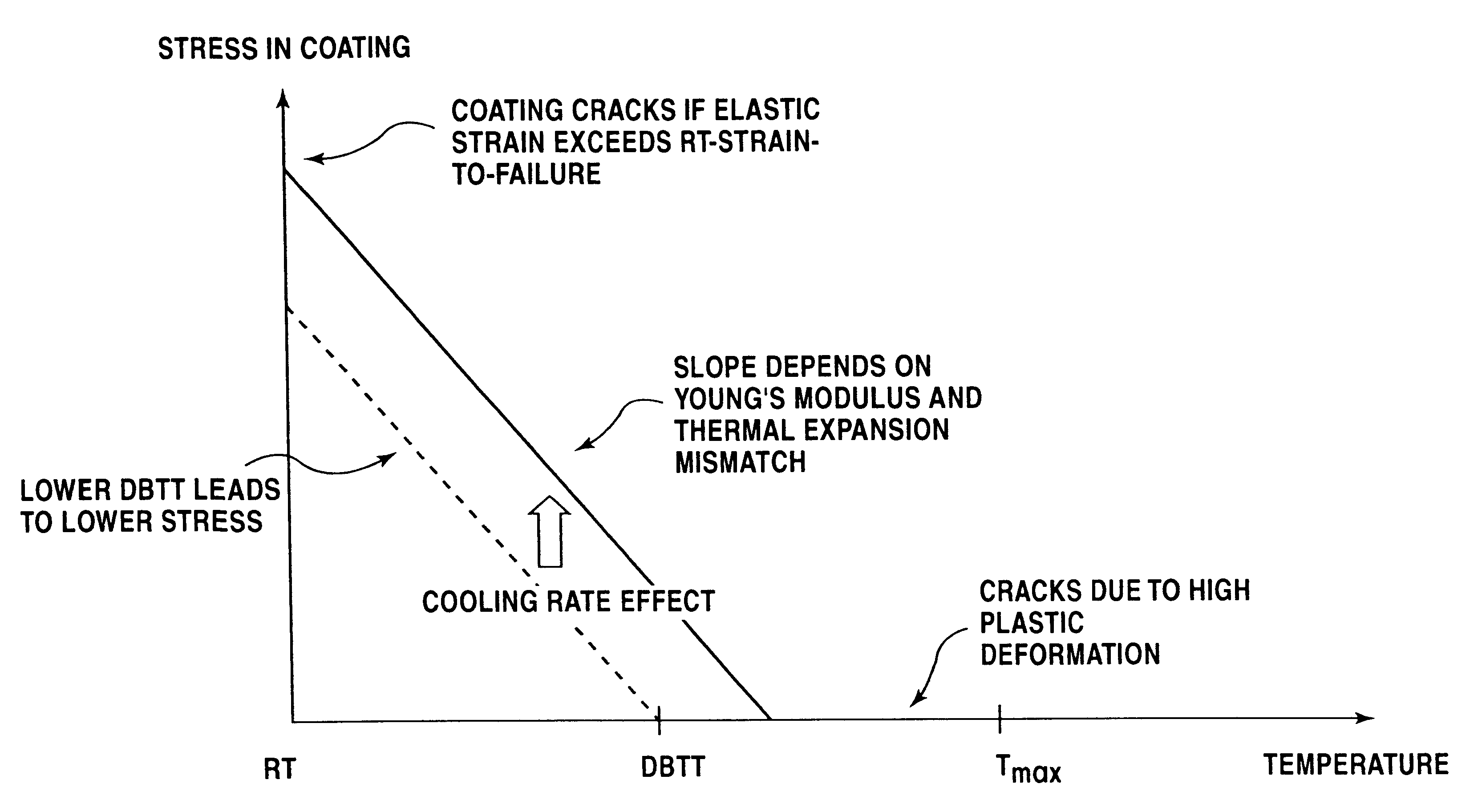
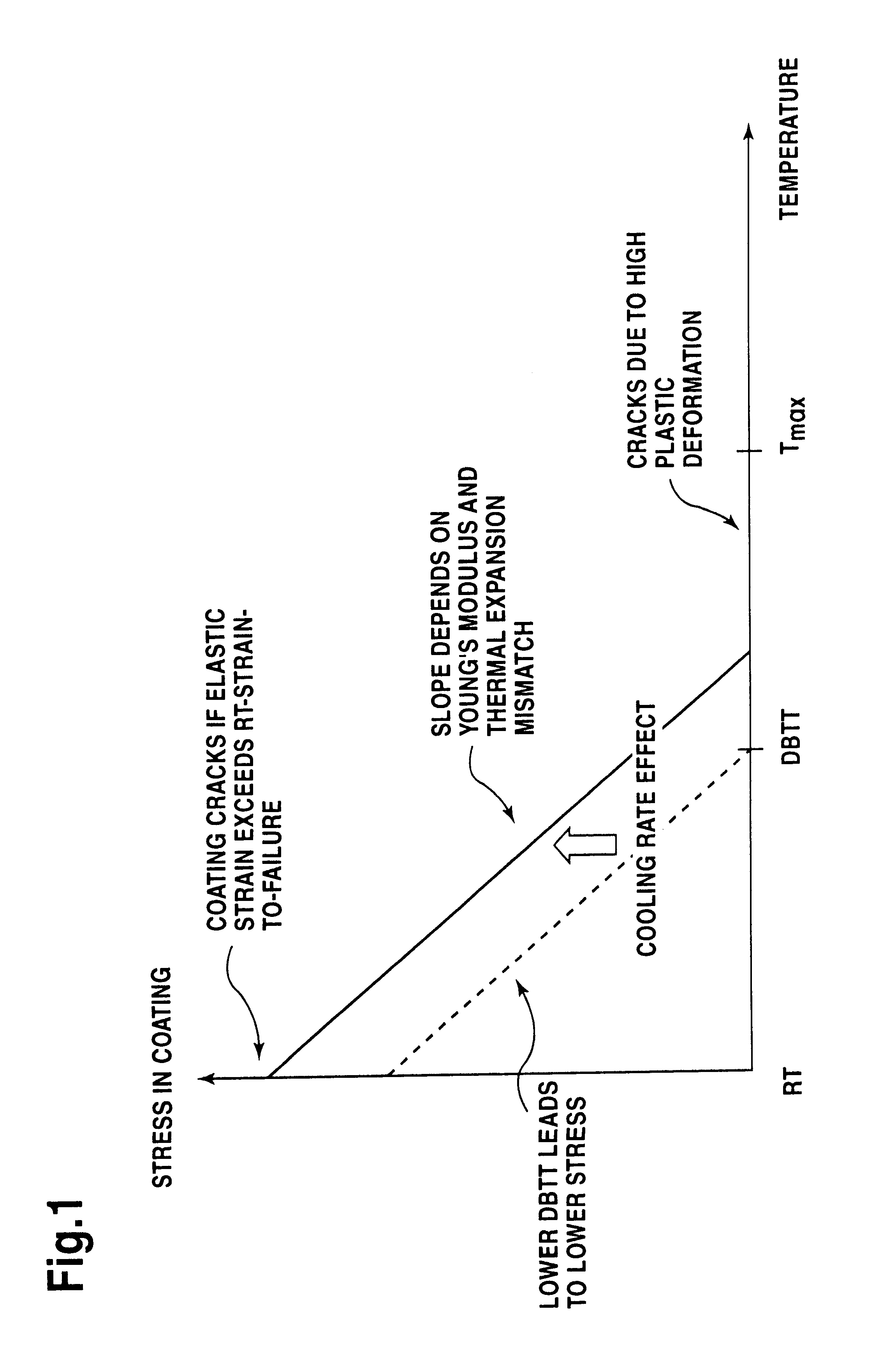
It is known that essentially two failure mechanisms control the thermomechanical fatigue (TMF) behavior of coated articles. One failure mechanism occurs in the low temperature region when stress builds up in the coat...


PUM

PropertyMeasurementUnit
temperaturesaaaaaaaaaa
temperatureaaaaaaaaaa

Abstract

The invention relates to a coating composition for superalloy structural parts, especially for gas turbine vanes and blades, which provides simultaneously excellent environmental resistance and highly improved thermomechanical behavior. The coating consists essentially of, by weight, 28-35% Co, 11-15% Cr, 10-13% Al, 0-1% Re, 1-2% Si, 0.2-1% Ta, 0.005-0.5% Y, 0-5% Ru, 0-1% Ca, 0-1% Mg, 0-0.5% La (or elements from the La series), 0-0.1% B, balance Ni and incidental impurities.

Description

1. Field of the InventionThe invention relates to an improved class of protective coatings for use on superalloy articles, such as gas turbine rotating blades and stationary vanes.Wide use of single crystal (SX) and directionally solidified (DS) hot-stage components has allowed increased turbine inlet temperature and therefore turbine efficiency. The improvement in high-temperature strength of these new superalloys involved an increased susceptibility of the alloy to sulfidation and oxidation. To restore environmental resistance to engine parts made from DS and SX alloys requires a new generation of high-temperature resistant coatings. Historically, aluminide or MCrAlY coatings (where M represents a transition element such as Ni, Co, Fe or mixtures thereof) have been applied by engine manufacturers to extend the useful life of hot section components.Due to their limited thickness (typically around 50 .about..mu.m) aluminide coatings do not offer sufficient oxidation and corrosion pr...

Claims


Application Information

Patent Timeline
Patent Type & Authority Patents(United States)
IPC IPC(8): C23C28/00C23C30/00
CPCC22C1/0433C22C19/058C23C28/3215C23C28/325C23C30/00C23C28/3455C23C28/321B22F2998/00Y10T428/12944B22F9/082
Inventor BOSSMANN, HANS-PETERSCHMUTZLER, HANS J.SOMMER, MARIANNESOMMER, CHRISTOPHKONTER, MAXIMHOLMES, PETERTOENNES, CHRISTOPH
Owner ANSALDO ENERGIA IP UK LTD
Why Eureka
Try Eureka