Thermionic generator

a generator and generator technology, applied in the field of thermoelectric generators, can solve the problems of low efficiency, space-charge effect, heat generated in the generator to be converted into electricity,

Inactive Publication Date: 2001-05-08
BOREALIS TECH LTD
View PDF0 Cites 72 Cited by
  • Summary
  • Abstract
  • Description
  • Claims
  • Application Information

AI Technical Summary

Problems solved by technology

All these devices use moving parts which are subject to friction and wear, and only a percentage of the heat generated is converted into electricity.
One of the problems associated with the design of thermionic converters is the space-charge effe

Method used


Image

  • Thermionic generator
  • Thermionic generator
  • Thermionic generator

Examples


Embodiment Construction

The following description describes a preferred embodiment of the invention and should not be taken as limiting the invention. Other embodiments obvious to those skilled in the art are included in the present invention.

Applicant has prior applications in this field, including the applications mentioned above and U.S. application Ser. No. 08 / 498,199, filed Jul. 5, 1995, herein incorporated by reference.

The method and apparatus of the present invention has numerous applications. For example, the alternator of the automobile could be replaced by a thermionic generator using the heat contained in the exhaust gases as a source of energy, which would lead to an increase in the efficiency of the engine. Another application is in domestic and industrial heating systems. These systems need a pump to circulate heated water around the system, which requires a source of power. The control circuitry regulating the temperature of the building being heated also requires power. These could both be ...


PUM


Abstract

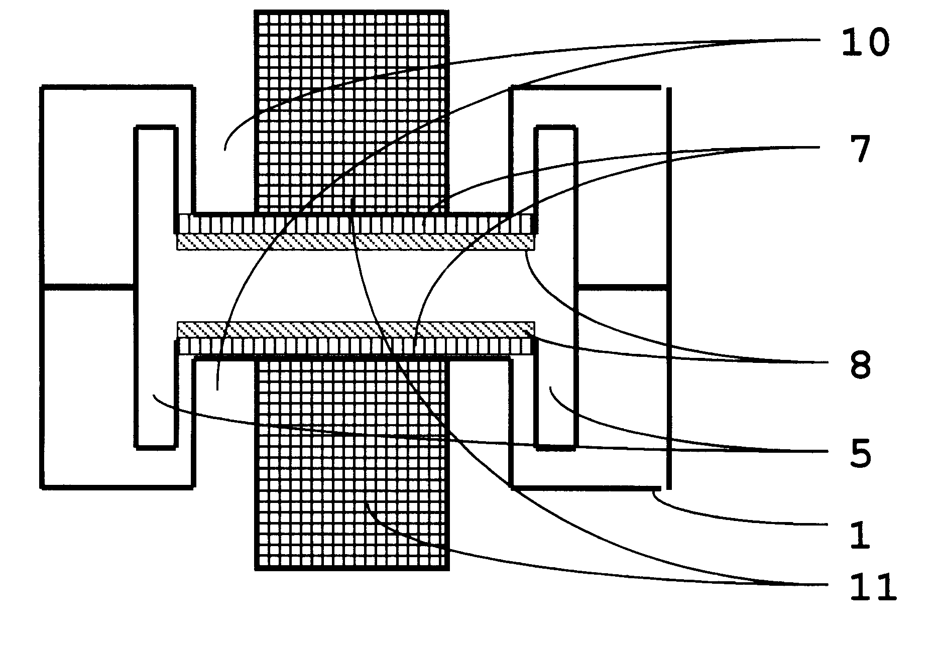
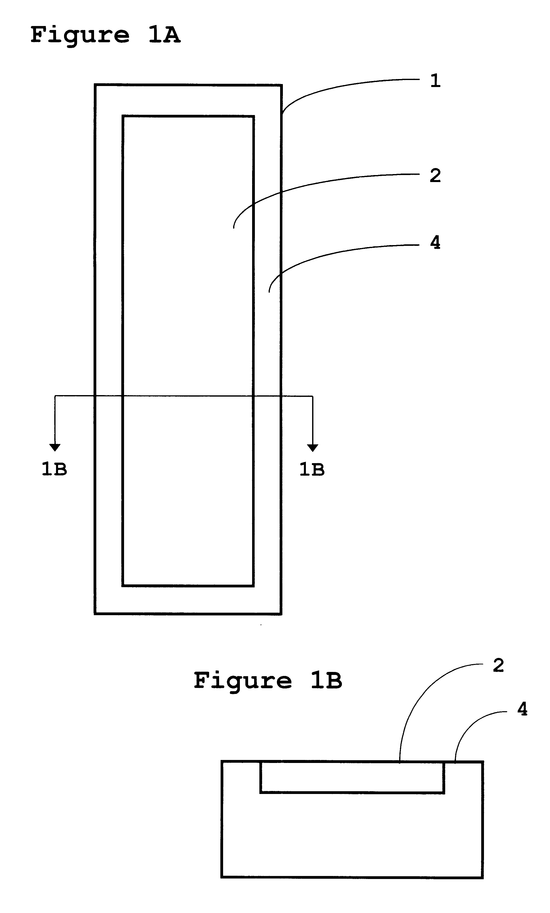
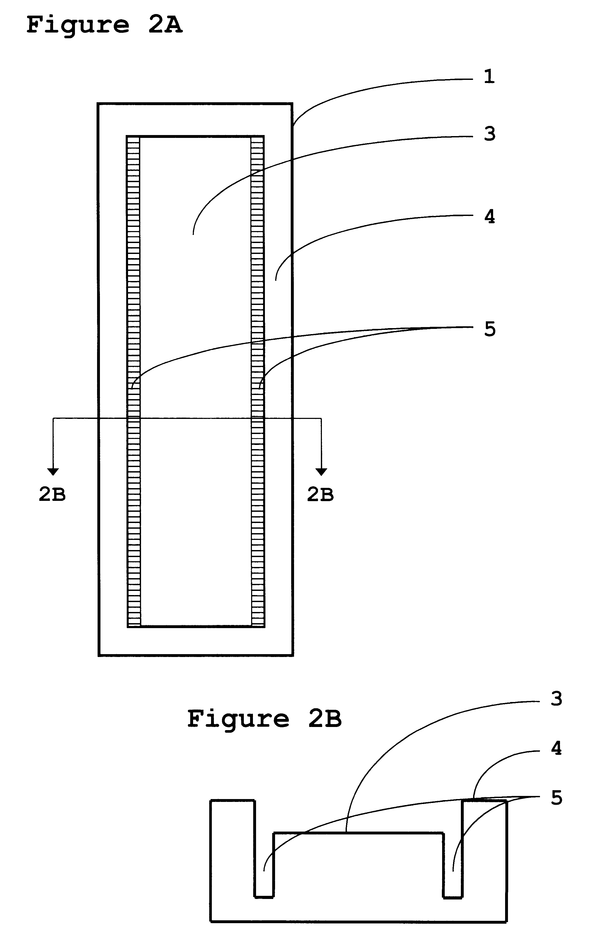
A method for building a thermionic converter comprises providing an electrode and creating a central depression of substantially uniform depth on a face of the electrode. A surface of the central depression is coated with a layer comprising a thermionic material. A second electrode comprising a face is also provided, wherein the face of the second electrode comprises a central depression of substantially uniform depth, wherein the central depression is coated with a layer comprising a thermionic material.

Description

1. Field of the InventionThe present invention is related to thermionic generators, and in particular to thermionic generators fabricated using micromachining methods.2. Description of The Related ArtMost electricity is generated at a power station by a process in which heat is used to convert water to steam. The steam expands through a turbine device causing it to rotate. This powers a generator unit, which produces electricity. The heat is provided by burning a fuel such as coal, oil, gas, or wood, or from nuclear, solar or geothermal energy.On a smaller scale, the generator unit may be powered by an internal combustion engine, such as a diesel or petrol driven motor. Similarly, the alternator used with the internal combustion engine in every type of automobile for providing electricity to the vehicle is powered by the rotating drive shaft of the engine.All these devices use moving parts which are subject to friction and wear, and only a percentage of the heat generated is convert...

Claims


Application Information

Patent Timeline
IPC IPC(8): G21H1/10G21H1/00H01J45/00
CPCG21H1/106H01J45/00
Inventor EDELSON, JONATHAN SIDNEY
Owner BOREALIS TECH LTD
Why Eureka
Try Eureka