Method and apparatus for traffic shaping in a broadband fiber-based access system

a technology of broadband fiber and access system, applied in the direction of transmission monitoring, frequency-division multiplex, data switching network, etc., can solve the problems of excessive increased complexity of queue control block 28, and increased complexity of buffer outside the blc. , to achieve the effect of increasing complexity, cost, power consumption and physical siz

Inactive Publication Date: 2001-05-08
RPX CLEARINGHOUSE
View PDF2 Cites 167 Cited by
  • Summary
  • Abstract
  • Description
  • Claims
  • Application Information

AI Technical Summary

Benefits of technology

In sum, the conventional system architecture, with respect to traffic flow, results in the installation of a set of large buffers that is complex, dependent on service characteristics and traffic classes, and rife with asso

Problems solved by technology

There are many situations in which it becomes clear that either the queues are not sufficiently large or that the queue control block 28 is excessively complex.
However, this creates a new problem: if the buffer devoted to UBR traffic in the BLC is full, then the additional buffer outside the BLC will begin to fill.
However, the bit rate of UBR traffic is not guaranteed (by definition), and therefore the CBR traffic in the additional outside buffer may have to wait an indefinite amount of time before being delivered to the customer, which would violate the BC or CBR service delivery parameters, causing a potential service failure, which is likely to be unacceptable to the end user.
Cl

Method used


Image

  • Method and apparatus for traffic shaping in a broadband fiber-based access system
  • Method and apparatus for traffic shaping in a broadband fiber-based access system
  • Method and apparatus for traffic shaping in a broadband fiber-based access system

Examples


Embodiment Construction

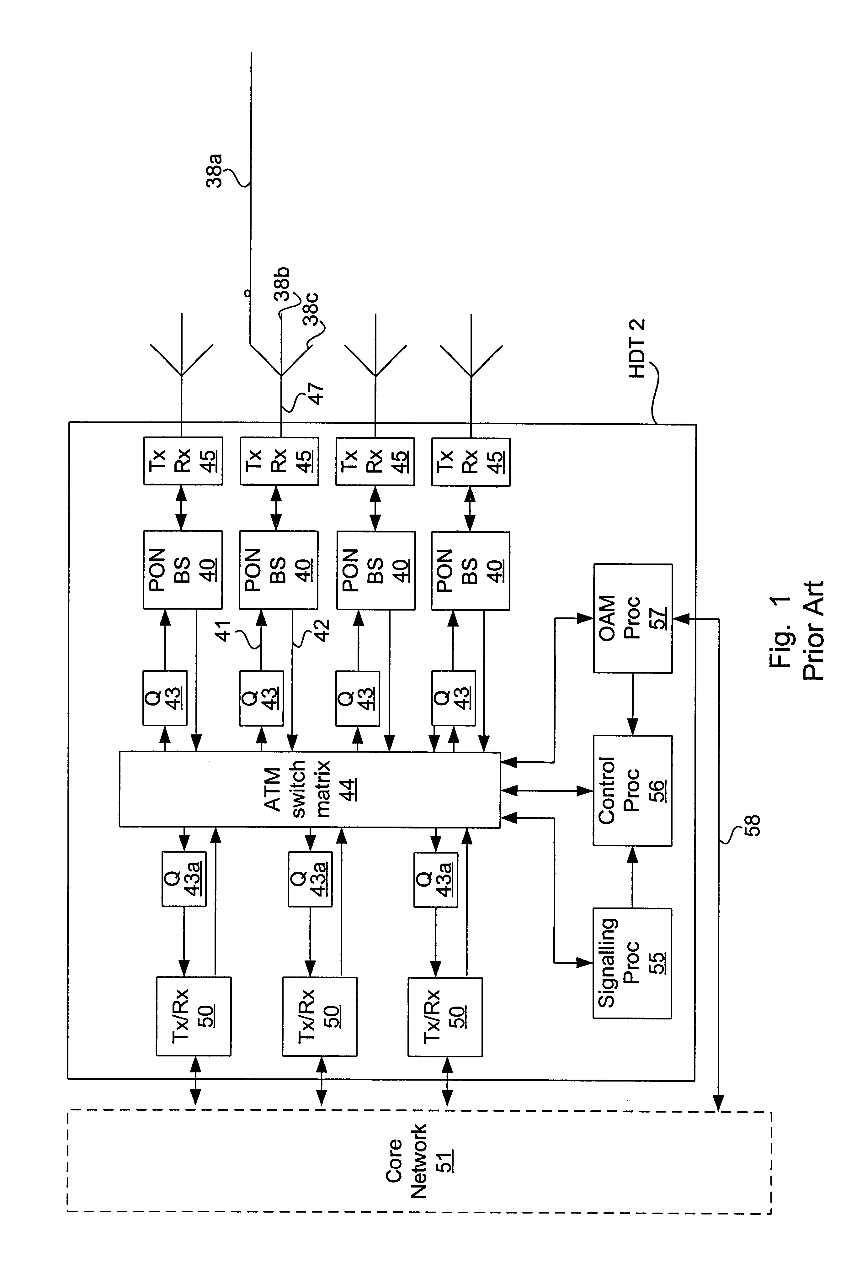
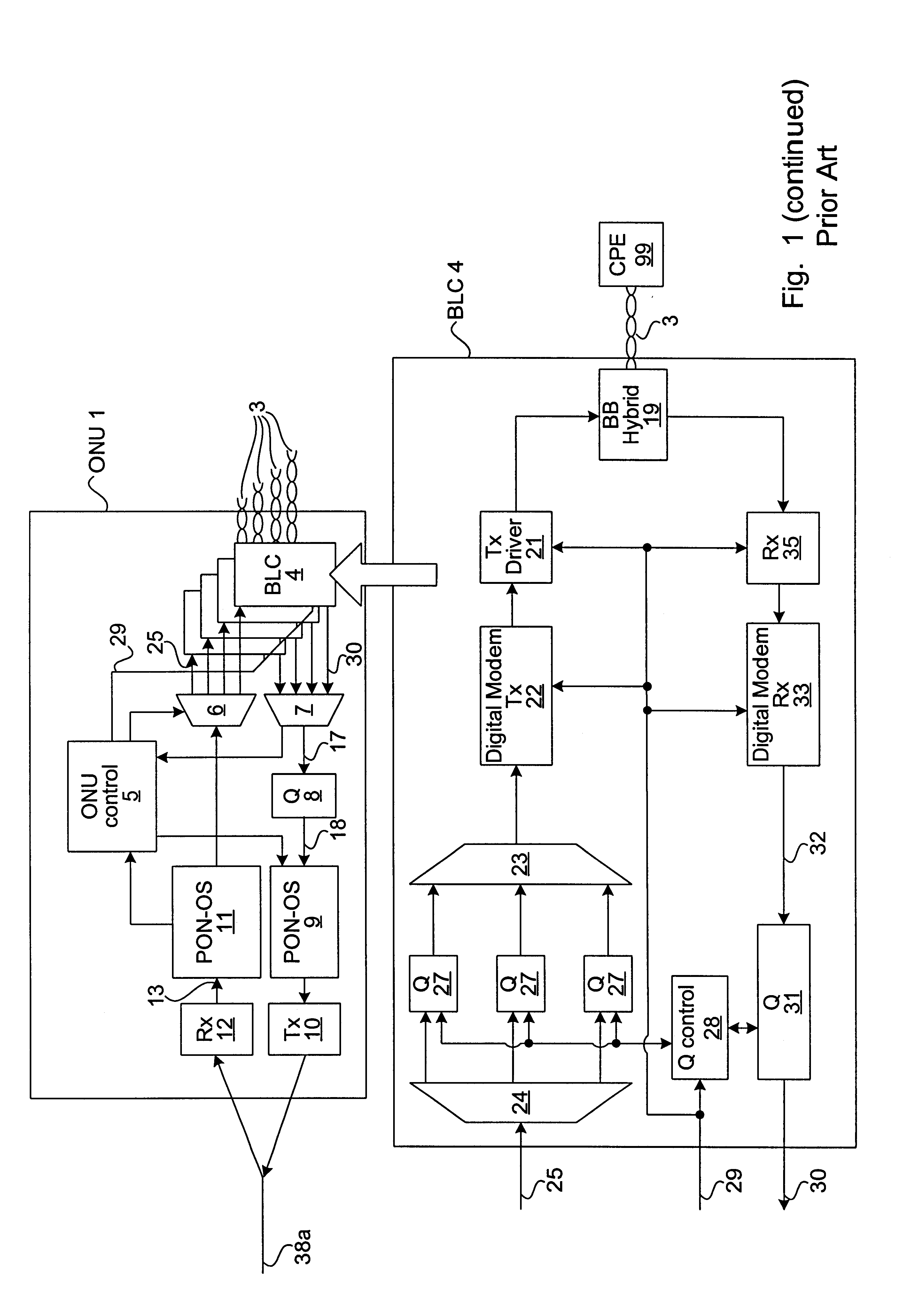
Reference is now made to FIG. 3, which depicts an access system in accordance with the present invention, comprising an HDT 83 connected between a core network 51 and a plurality of ONUs 59 (only one of which is shown) in a PON configuration. A SONET ring or a plurality of individual point-to-point links can also be used to interconnect the ONUs and HDT. Without loss of generality, it can be assumed that a bidirectional optical fiber feeder 47 connects the HDT 83 to an optical splitter (not shown), which passively splits / joins a plurality of fiber umbilicals 38a,b,c leading to respective ONUs. Alternatively, there may be a pair of dedicated optical fibers along each link to separately transport upstream and downstream traffic.

As in the prior art, the HDT 83 comprises a switch matrix 44 connected in a known way to a signalling processor 55, a control processor 66 and an OAM processor 57 connected by its own control line 58 to the management layer of the core network 51. The control p...


PUM


Abstract

The invention is a novel method and apparatus for controlling the flow of traffic between a host digital terminal (HDT) and a plurality of optical network units (ONUs). Each ONU is connected to the HDT by optical fiber and to a plurality of subscribers by a respective plurality of subscriber drops (typically pre-existing copper twisted pairs). The bandwidth on the fiber, although large, is usually inferior to the total bandwidth that can be transmitted across the subscriber drops. Therefore, both upstream and downstream traffic may become congested at various "choke points" under certain circumstances of usage. Ordinarily, the data is buffered at the choke points, leading to the installation of large queues within each ONU. This solution is not only expensive, but is inadequate since the required queue size is dependent on the maximum transaction size, which has no hard upper bound. In contrast, the present invention provides a traffic shaper located in the HDT, which gives centralized control of the traffic flowing to and from the ONUs. Consideration of the priority and destination of each traffic cell is taken into account by the traffic shaper to ensure that the capacity of the fiber and of the individual drops is never exceeded, irrespective of the transaction sizes, thereby eliminating the need for costly buffers in the outside plant. Any maintenance or repairs of the traffic shaper can be easily effected without field visits, due to its centralized location.

Description

The present invention relates to broadband communication networks, and particularly to a method and apparatus for controlling traffic flow through the network in order to minimize the cost of buffering data in outside-plant components.In order to enable the delivery of broadband services by present and future fiber-based data transport systems, optical fiber is being extended deeper into the network, having led to the deployment of optical network units (ONUs) to a point within several hundred (or a few thousand) feet of the end user. The ONUs each serve a plurality of subscribers and communicate via a fiber optic feeder cable with a host digital terminal (HDT) that is usually placed in a central office location and is connected to the remainder of the network. The relatively short drop length between the ONUs and the individual subscribers reduces frequency-dependent signal losses on the residual copper twisted pairs and allows the transmittal of high-bandwidth data across these dr...

Claims


Application Information

Patent Timeline
IPC IPC(8): H04Q11/04H04L12/56H04Q11/00H04L69/14
CPCH04L49/205H04L49/254H04L49/255H04L49/3081H04L49/50H04Q11/0478H04L49/201H04L49/30H04L2012/5605H04L2012/561H04L2012/568H04Q11/0067H04Q11/0071
Inventor GRAVES, ALAN FRANKTIMMS, ANDREW JOCELYNFISHER, DAVID ANTHONY
Owner RPX CLEARINGHOUSE
Why Eureka
Try Eureka