Clocking technique for reducing sampling noise in an analog-to-digital converter

a clocking technique and digital converter technology, applied in the field of improving the operation of analogtodigital converters, can solve the problems of serious operational problems adversely affecting the regularity of the adc clock's clock frequency adcclk, and invariably entering the system, so as to improve the resolution, reduce the cost, and improve the effect of noise reduction

Inactive Publication Date: 2001-05-15
LUCENT TECH INC
View PDF7 Cites 49 Cited by
  • Summary
  • Abstract
  • Description
  • Claims
  • Application Information

AI Technical Summary

Benefits of technology

An added advantage of the present invention is the low cost and ease with which it may be implemented within existing ADC control logic. That is, with the mere addition of an RS latch and supporting digital logic circuitry, improved resolution may be achieved at low cost and with, essentially, the same ADC.
These and other advantages and features of the invention will be more clearly understood from the following

Problems solved by technology

Notwithstanding the efforts of the PLL circuit 14 to so regulate the ADC clock ADCCLK, noise invariably enters the system and adversely affects the regularity of the ADC clock's clock frequency ADCCLK.
Jitter, as it in known in the art, relates to the non-fixed frequency of the clock pulse used to drive the sampling and conversion processes; in this case, the ADC clock ADCCLK If the frequency of the ADC clock ADCCLK is not precisely fixed, it may cause serious operational problems for the ADC, reducing accuracy and resolution.
More specifically, when the ADC clock ADCCLK frequency is not fixed during the sampling process, the portion of the signal being sampled varies with the frequency, thus resulting in a tainted evaluation of the analog signal.
Furthermore, in as much as the counter 10 controls the analog-to-digital conversion process, any jitter present within the ADC clock pulse ADCCLK will result in the jitter actually modulating the analog signal that is being held on the capacitor within the sample and hold circuitry.
This modulation worsens as the sampling frequency increases, thus adding to the adverse affects of the sampling noise.

Method used


Image

  • Clocking technique for reducing sampling noise in an analog-to-digital converter
  • Clocking technique for reducing sampling noise in an analog-to-digital converter
  • Clocking technique for reducing sampling noise in an analog-to-digital converter

Examples


Embodiment Construction

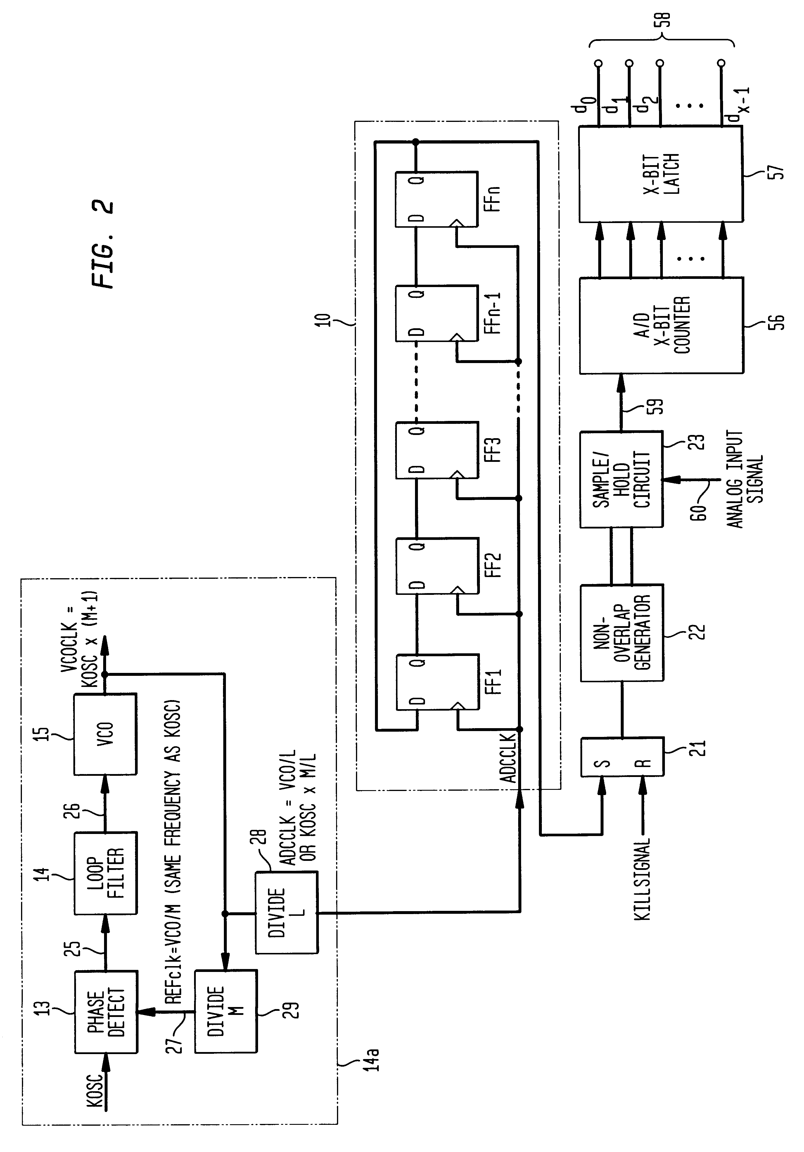
A preferred embodiment of the present invention will now be described with reference to FIGS. 2-4. Other embodiments may be realized and structural, or logical changes may be made to the disclosed embodiment without departing from the spirit or scope of the present invention.

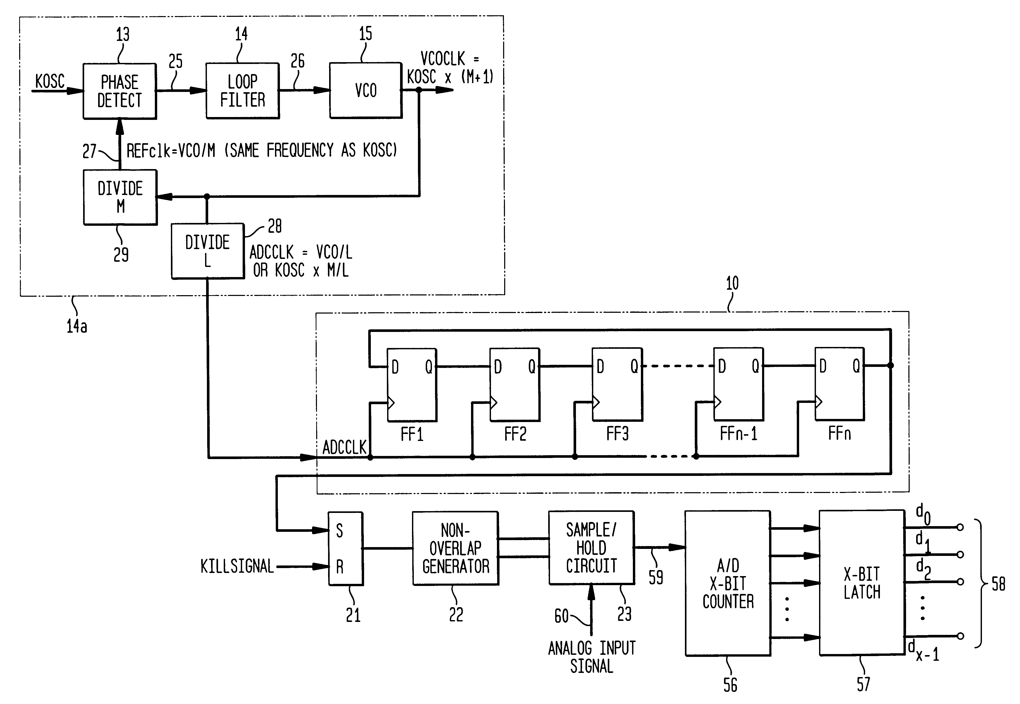
FIG. 2 depicts a conventional rotating ones counter 10, of n stages, consisting of n successive D flip-flops FF1, FF2, . . . FFn, where n may be any number that allows the ADC to satisfactorily perform the particular conversion process being employed. The output of each D flip-flop Q is coupled to the input of the D flip-flop immediately following. The output of the n.sup.th D flip-flop Q is coupled to the input of the first D flip-flop D. The clock input of each D flip-flop FF1, FF2, . . . FFn is coupled to the noisy ADC clock ADCCLK Therefore each of the n D flip-flops receives the same common clock pulse ADCCLK.

The ADC clock ADCCLK is generated by the PLL circuit 14a, wherein the ADC clock is maintained at a ...


PUM


Abstract

A method and apparatus are disclosed for improving the operation of an analog-to-digital converter ("ADC"). A separate "clean" oscillator clock is to be used in combination with a "noisy" ADC clock being regulated by a phase-locked-loop (PLL) circuit. The "noisy" ADC clock drives the digital control logic and also turns on the sample signal for the purpose of sampling. The second clock, which has a substantially fixed (i.e., "clean") frequency is used to generate a short pulse, the leading edge of which turns off the sample signal, thereby providing an improved sampling process with greater resolution. The interaction of the two clocks is controlled with digital logic circuitry.

Description

1. Field of the InventionThe present invention relates to improving the operation of analog-to-digital converters ("ADCs"). More specifically, it relates to the removal of clock noise from the sampling process, thereby improving the resolution of the ADC.2. Description of the Related ArtWhen digital processing hardware receives an analog signal, it first digitizes the analog signal with an analog-to-digital converter (ADC). After the signal has been digitized, it may be forwarded to downstream digital processing circuitry for further analysis and / or manipulation. Not surprisingly, in many applications, it is desirable to use an inexpensive ADC which produces high resolution digital samples at a relatively high rate.Currently, several different types of ADCs are used in the art. This nonexclusive list includes successive approximation ADCs, dual slope integrating ADCs, and charge balancing ADCs.Successive approximation ADCs provide a fast analog-to-digital conversion of a momentary v...

Claims


Application Information

Patent Timeline
Patent Type & Authority Patents(United States)
IPC IPC(8): H03M1/06H03M1/12H03M1/08
CPCH03M1/0836H03M1/12
Inventor SMITH, MALCOLM H.MO, JIANCHENG
Owner LUCENT TECH INC
Why Eureka
Try Eureka