Aluminum laminate

a technology of aluminum laminate and aluminum plate, applied in the field of aluminum laminate, can solve the problems of untreated aluminum having a corrosion resistance which does not match, existing surface treatments for aluminum do not provide the specific combination of formability, corrosion resistance, ultra-violet light resistance, scratch resistance, etc., and achieve the effect of reducing the number of defects

Inactive Publication Date: 2001-05-22
ARCONIC INC
View PDF7 Cites 54 Cited by
  • Summary
  • Abstract
  • Description
  • Claims
  • Application Information

AI Technical Summary

Problems solved by technology

However, untreated aluminum has a corrosion resistance which does not match up against certain non-corrosive metals, e.g., such as stainless steel in some applications.
Aluminum can be surface treated to provide excellent corrosion resistance, but, in some cases, existing surface treatments for aluminum do not provide the specific combination of formability, corrosion resistance, ultra-violet light resistance, scratch resistance, and ease of large-scale manufacture.
In the area of automotive trim, cost and light weight are critical factors.
But, products achieving the required salt resistance, ultra-violet light resistance, scratch resistance, and formability at a reasonable cost have proven to be a challenging obstacle.
Aluminum has a certain level of corrosion resistance, and the various available coatings cannot supply the scratch resistance and formability required.
Further, the pre-treatments, brightening steps, and coating materials add an additional cost.
One would have expected that aluminum, which is high in galvanic activity, and stainless steel, which is a passive material, would have created an electrical battery, in effect, and destructively acted on the aluminum.
Bi-metal fabrications, which are mechanically joined together, e.g., by rolling, suffer from problems of galvanic corrosion between the two dissimilar metals.
Below about 0.001 inches (1 mil) thick stainless steel, the laminated product of the present invention still may be fabricated, but the cost of the stainless steel increases significantly.
Below about 0.002 inches (2 mils) thick stainless steel or non-corrosive metal top sheet, the metal becomes more susceptible to tearing, especially in continuous coil operations.
The disadvantage is added cost if greater corrosion resistance and adhesion are unnecessary.

Method used


Image

  • Aluminum laminate
  • Aluminum laminate
  • Aluminum laminate

Examples


example ii

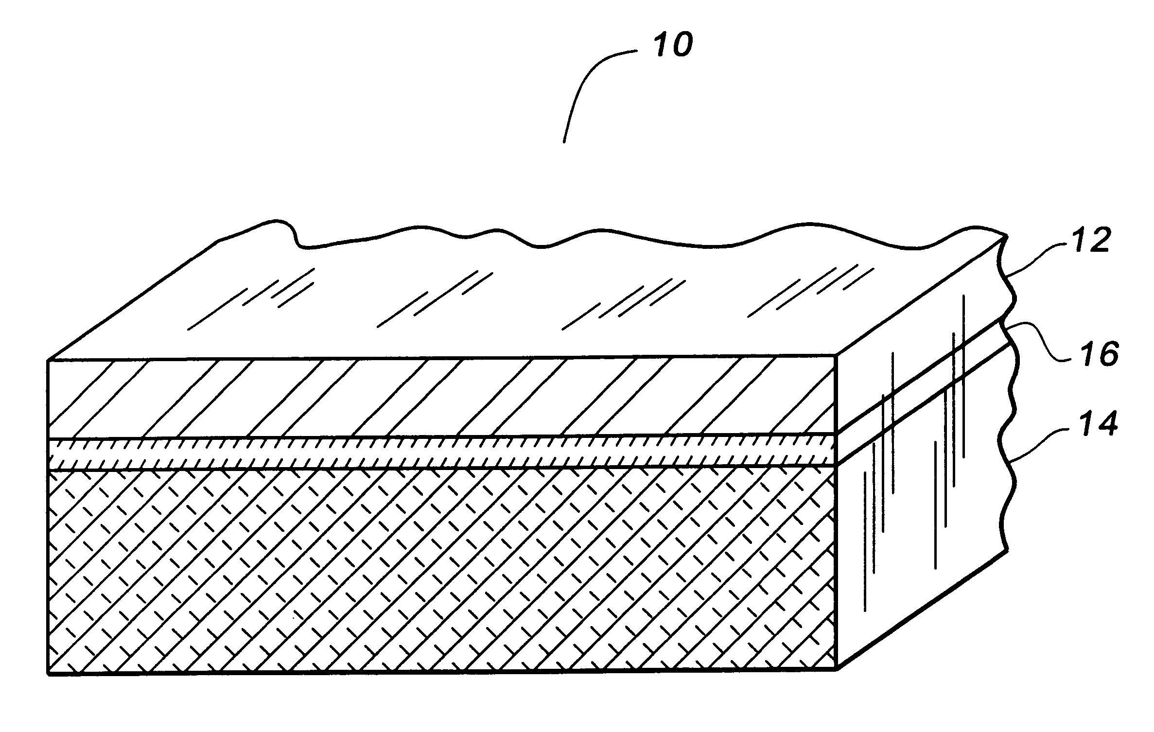
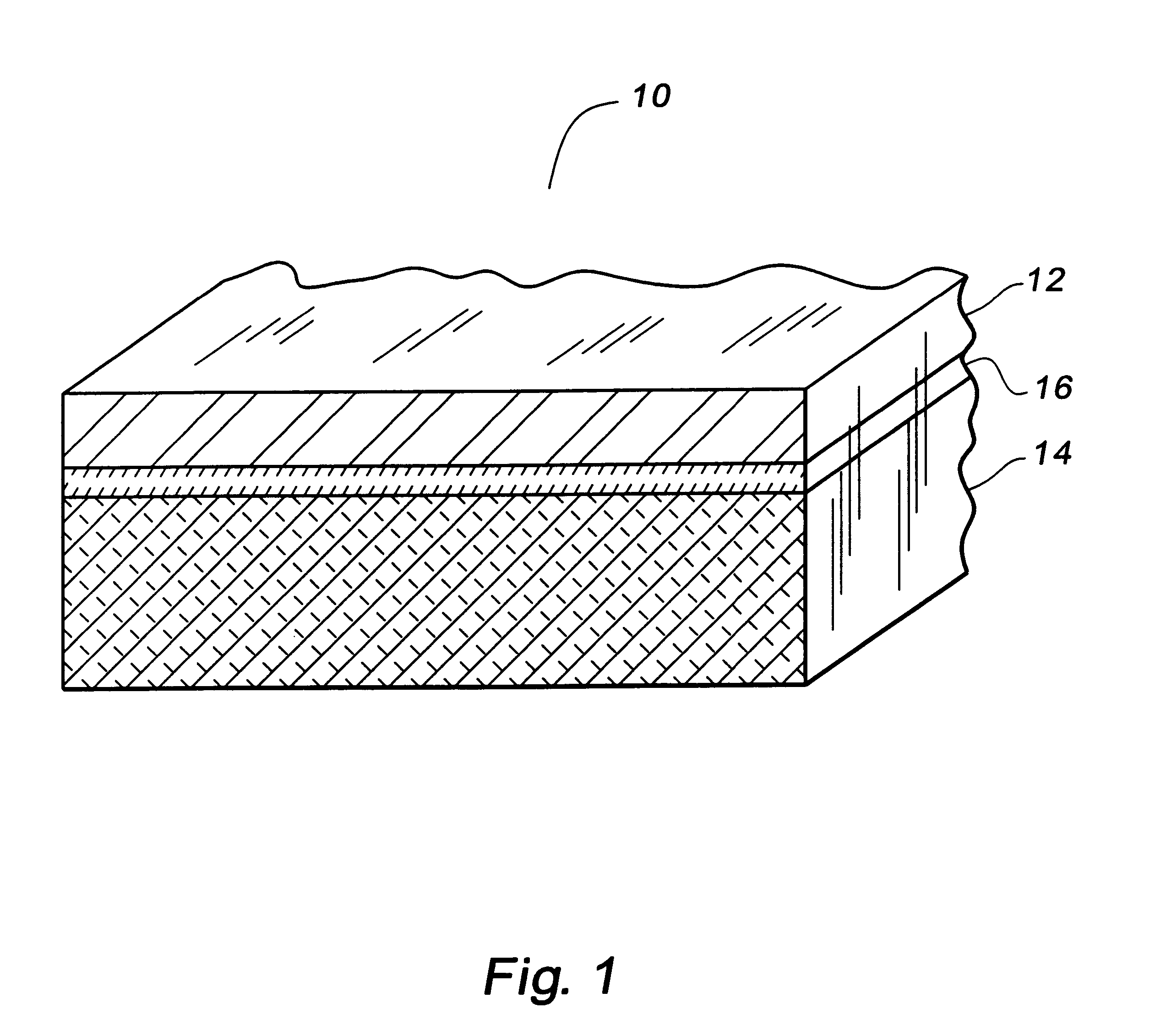
Three different material foil samples, (1) 316 Stainless Steel, (2) 304 Stainless Steel, and (3) nickel, were obtained from Goodfellow Cambridge Limited of Cambridge, England.

The 316 Stainless Steel (316SS) was composed of Fe / Cr18 / Ni10 / Mo3 in a foil 0.05 mm thick. The 316SS foil had an annealed temper and came in a coil width of 300 mm.

The 304 Stainless Steel (304SS) was composed of Fe / Cr18 / Ni10 in a foil 0.05 mm thick. The 304SS foil had a hard temper and came in a coil width of 200 mm.

The nickel was composed of 99.0% purity nickel in a foil 0.05 mm thick. The nickel had an annealed temper and came in a coil width of 300 mm.

The three different material foil samples were laminated onto 5657 aluminum alloy 0.020 inch gauge from the Aluminum Company of America master coil lot no. 721891 using a thin double backed adhesive tape 3M Double-backed Tape (Green release paper) from 3M Corporation and Ciba Geigy adhesive systems obtained from Ciba-Geigy of East Lansing Michigan: Araldite AV 8...

example iii

Stainless steel or nickel foil samples were laminated onto 5657 aluminum alloy. Parts remaining flat were scored with an X for salt spray tests. Some parts were formed in a roll former, and some of those were exposed to 1000 hours of continuous salt spray without a scored X. All parts had sealed edges. A summary of results follows in Table I, with salt spray time referring to time to corrosion.

From the Example III and the Table I data, the 304 Stainless Steel laminated to aluminum may last longer in salt spray than 316 or nickel metal, perhaps because of less difference in the galvanic series between 304 and aluminum. The nickel metal may adhere better with the adhesives selected, and nickel metal may be the preferred overall selection. The concept of laminating a more inert metal to aluminum is technically viable with the proper selection of adhesive and metal.

example iv

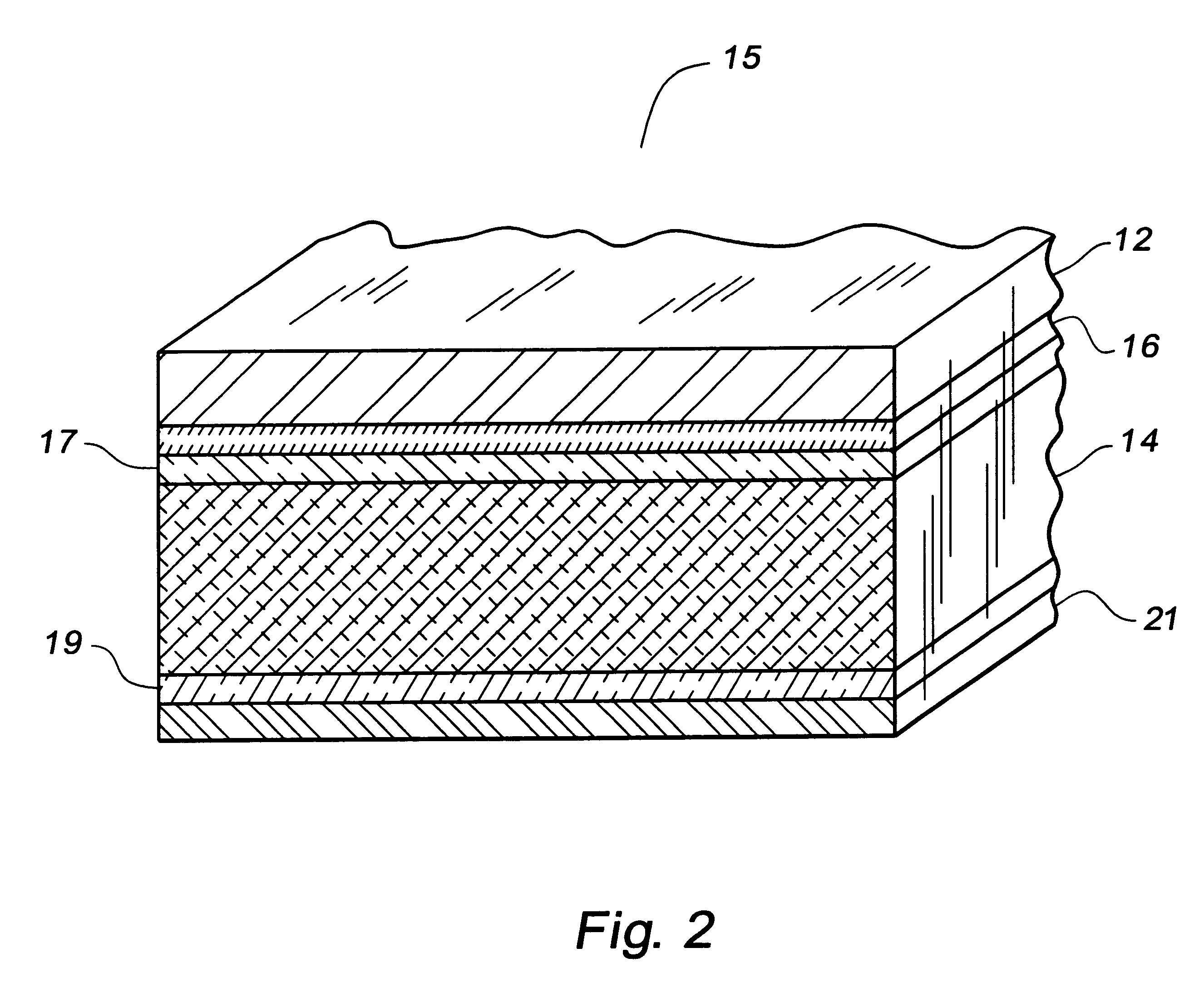
An aluminum of 5657 aluminum alloy was cleaned in Henkel A-31K alkaline non-etch aluminum cleaner. Conversion coating was not performed in this case. Adhesive was applied via a draw down bar in a standard laboratory method where coating or adhesive is rolled or smeared onto the surface of a sheet with a bar. The adhesive was applied in a production thickness of between about 0.5 and 1.0 mils. The adhesive was cured in an oven according to the procedure in the respective commercial supplier data sheets. Immediately upon removal from the oven, the adhesive coated aluminum sheet was placed into a "wringer" type roll setup along with the stainless steel sheet. The materials were forced together as the aluminum and stainless sheets proceeded between the 2 rolls.

After assembling, the samples were tested by the following procedure:

This was repeated for 30 cycles. Over weekends, parts were retained in the humidity cabinet.

Table II presents a summary of the adhesion testing versus adhesive t...


PUM

PropertyMeasurementUnit
thicknessaaaaaaaaaa
thicknessaaaaaaaaaa
thicknessaaaaaaaaaa

Abstract

A bright finish aluminum alloy on high strength aluminum or aluminum alloy lamination is disclosed including a bright finish top sheet, a high strength aluminum or aluminum alloy substrate, and an adhesive bonding the bright finish metal top sheet to the high strength aluminum or aluminum alloy substrate to provide a bright finish aluminum on high strength aluminum or aluminum alloy lamination product having brighter finish than a sheet product of said high strength aluminum or aluminum alloy and higher strength than a sheet product of said bright finish aluminum of the same thickness as said lamination product, wherein said lamination product withstands galvanic corrosion. In one aspect, the bright finish metal top sheet is 5657 aluminum foil. In one aspect, the high strength aluminum alloy is 5182 alloy sheet.

Description

1. Technical FieldThis invention relates to an aluminum laminated product. In one aspect, this invention relates to a bright finish, high strength aluminum or aluminum alloy lamination and a method of making such a bright finish, high strength aluminum or aluminum alloy lamination.2. BackgroundStainless steel dominates in many markets as the material of choice because of its corrosion resistance and bright finish.However, stainless steel suffers from problems of high cost and heavy parts.INTRODUCTION TO THE INVENTIONCurrent aluminum technology is influenced by the fact that bright dipping and anodizing are very sensitive to aluminum alloy composition, thereby influencing the alloys of choice for bright dipping and anodizing. A few high purity alloys are preferred. The high purity alloys are relatively soft, thereby influencing their use in high strength applications.Aluminum is the preferred design choice for some metal applications because of light weight and lower cost than stainl...

Claims


Application Information

Patent Timeline
Patent Type & Authority Patents(United States)
IPC IPC(8): B32B15/08
CPCB32B15/08Y10S428/926Y10S428/925Y10T428/12639Y10T428/12569Y10T428/12757Y10T428/12764Y10T428/31678Y10T428/31681Y10T428/31522
Inventor SERAFIN, DANIEL L.SCHULTZ, PAUL B.ASKIN, ALBERT L.STANKO, DONALD J.
Owner ARCONIC INC
Why Eureka
Try Eureka