Motor-driven medical instrument with flexible shaft

a technology of flexible shafts and motors, which is applied in the direction of surgical forceps, bearing unit rigid support, dental surgery, etc., can solve the problem of high investment costs, and achieve the effect of reducing the investment cos

Inactive Publication Date: 2001-06-12
KARL STORZ GMBH & CO KG
View PDF14 Cites 63 Cited by
  • Summary
  • Abstract
  • Description
  • Claims
  • Application Information

AI Technical Summary

Benefits of technology

is to improve a generic type medical instrument in suc

Problems solved by technology

Therefore, in the past two instruments, one in which the hand piece is disposed at an angle to the instruments and one i

Method used


Image

  • Motor-driven medical instrument with flexible shaft
  • Motor-driven medical instrument with flexible shaft

Examples


Embodiment Construction

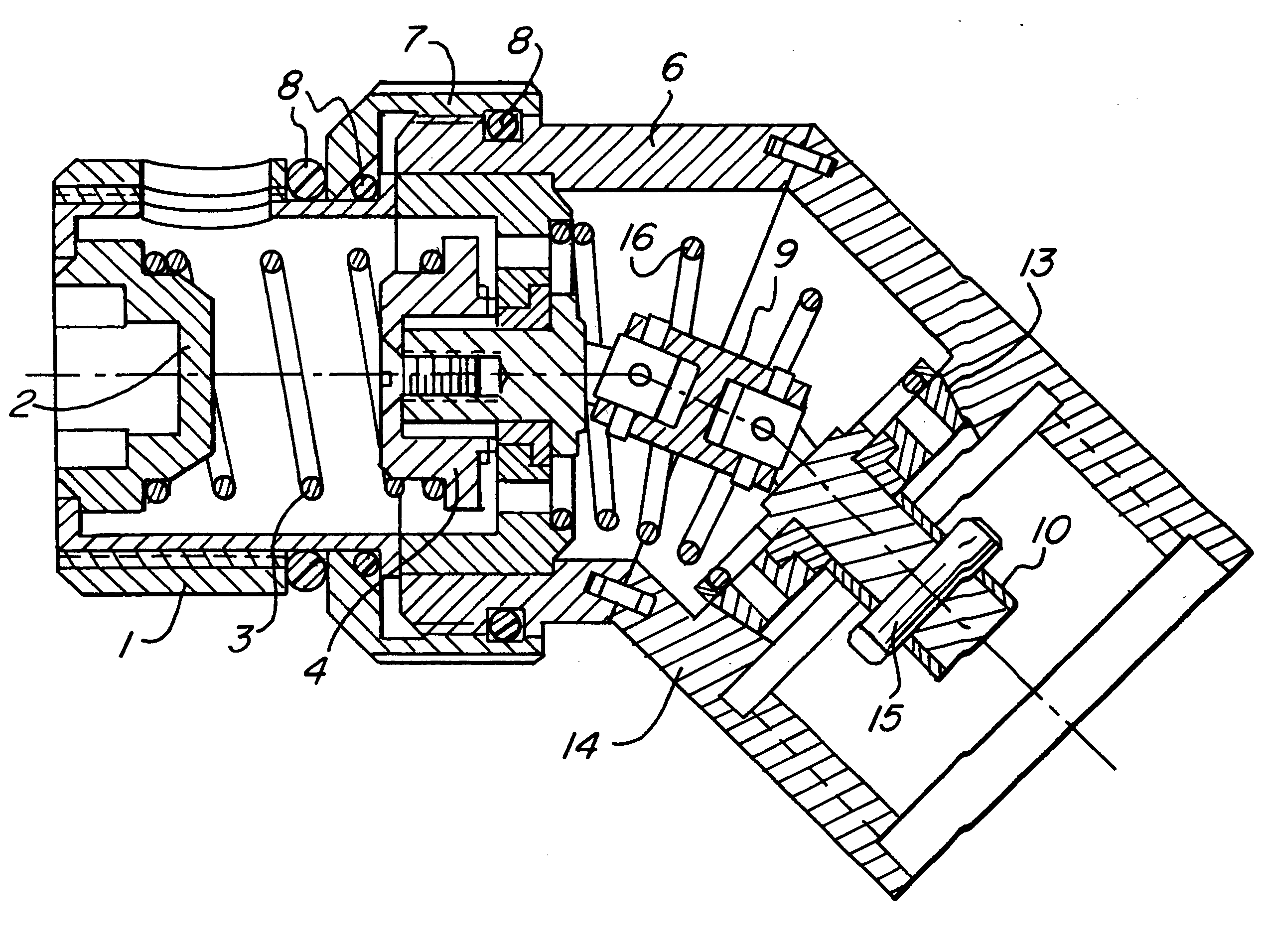
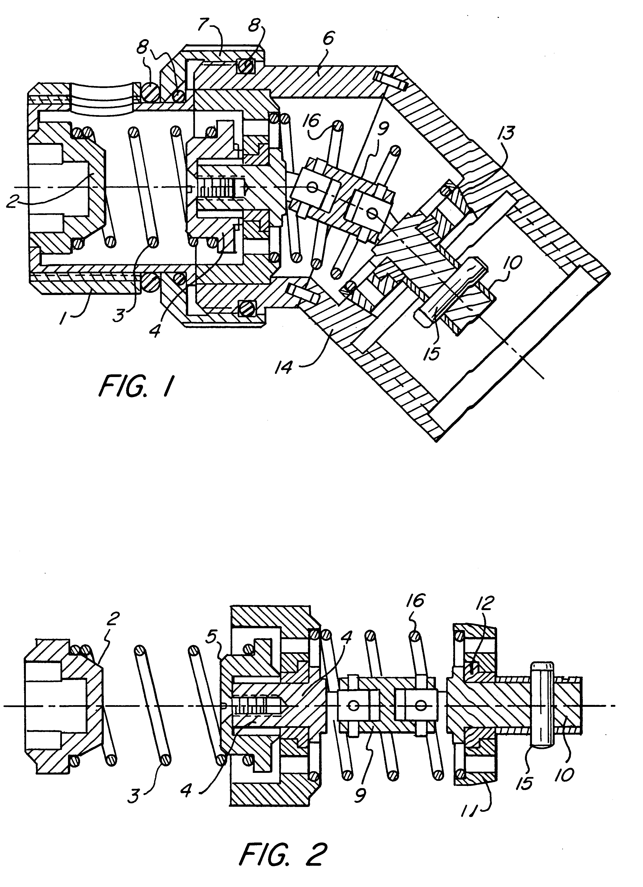
The object of the present invention is to improve a generic type medical instrument in such a manner that the cost of the investment is reduced.

An invented solution to this object is set forth in the alternative independent claims 1 and 2.

In the solution set forth in claim 1, the motor is connected in an as such known detachable manner to the shaft. A bend can be inserted between the motor shaft and the shaft disposed in the instrument.

In this way, the motor can be flanged both coaxially to the instrument and by means of the bend to the instrument in such manner that it is connected at an angle.

In the solution set forth in claim 2, a flexible bend is inserted between the motor and the shaft. By adjusting this bend, the motor can be disposed coaxially to the shaft as well as at any desired angle.

Claim 3 characterizes that the motor is disposed in an as such known manner in a hand piece of the instrument, thereby improving the instrument egonomically, because the operating person can ...


PUM


Abstract

Disclosed is a medical instrument having at least one surgical element, such as a knife or the like disposed at the distal end thereof, a motor disposed at the proximal end thereof, and a shaft which connects the shaft of the motor to the shaft of the surgical instrument in such a manner that the surgical element is rotated.According to the invention either the motor is detachably connected to said shaft of the said surgical element in an as such known manner so that a bend can be inserted between the motor shaft and said shaft disposed in the instrument or that a flexible bend is inserted between the motor and the shaft in such a manner that the motor shaft and the shaft disposed in the instrument includes an adjustable angle.

Description

The present invention relates to a medical instrument as set forth in the generic part of the alternative independent claims 1 and 2.Medical instruments of the class presupposed in the generic part of the alternative independent claims 1 and 2 are employed, by way of illustration, in the form of a so-called sheaver. Instruments of this type have a motor disposed at their proximal ends. The driven shaft of this motor is connected via a transmission shaft disposed in the instrument or connected directly to at least one surgical element, such as a knife, an ablating element or the like, disposed at the distal end.STATE OF THE ARTThe known generic instruments are either designed in such a manner that the engine is disposed coaxially to the shaft in the instrument or that the motor driven shaft and the shaft in the instrument include a specific, predetermined, unchangeable angle. Usually the motor is disposed in a hand piece with which the physician holds the instrument.Which of the poss...

Claims


Application Information

Patent Timeline
IPC IPC(8): A61B17/32A61C1/18A61C1/08F16C35/04F16C35/067F16C1/04F16C1/00A61B17/28A61B17/04F16C1/18
CPCA61B17/32A61C1/18A61C1/185F16C1/04F16C35/067A61B2017/2927F16C2316/10
Inventor STORZ, KARL
Owner KARL STORZ GMBH & CO KG
Why Eureka
Try Eureka