
Handle for inoculating loop

a technology of inoculation loop and handle, which is applied in the field of inoculation loop assembly, can solve the problems of undesired amount of time to assemble, undesired complexity and cost of fabrication of typical prior art handles, etc., and achieves the effects of reducing molding cost, reducing assembly cost, and limiting the movement of the plunger

Inactive Publication Date: 2001-06-12
BIO PLAS
View PDF3 Cites 8 Cited by
  • Summary
  • Abstract
  • Description
  • Claims
  • Application Information

AI Technical Summary

Benefits of technology

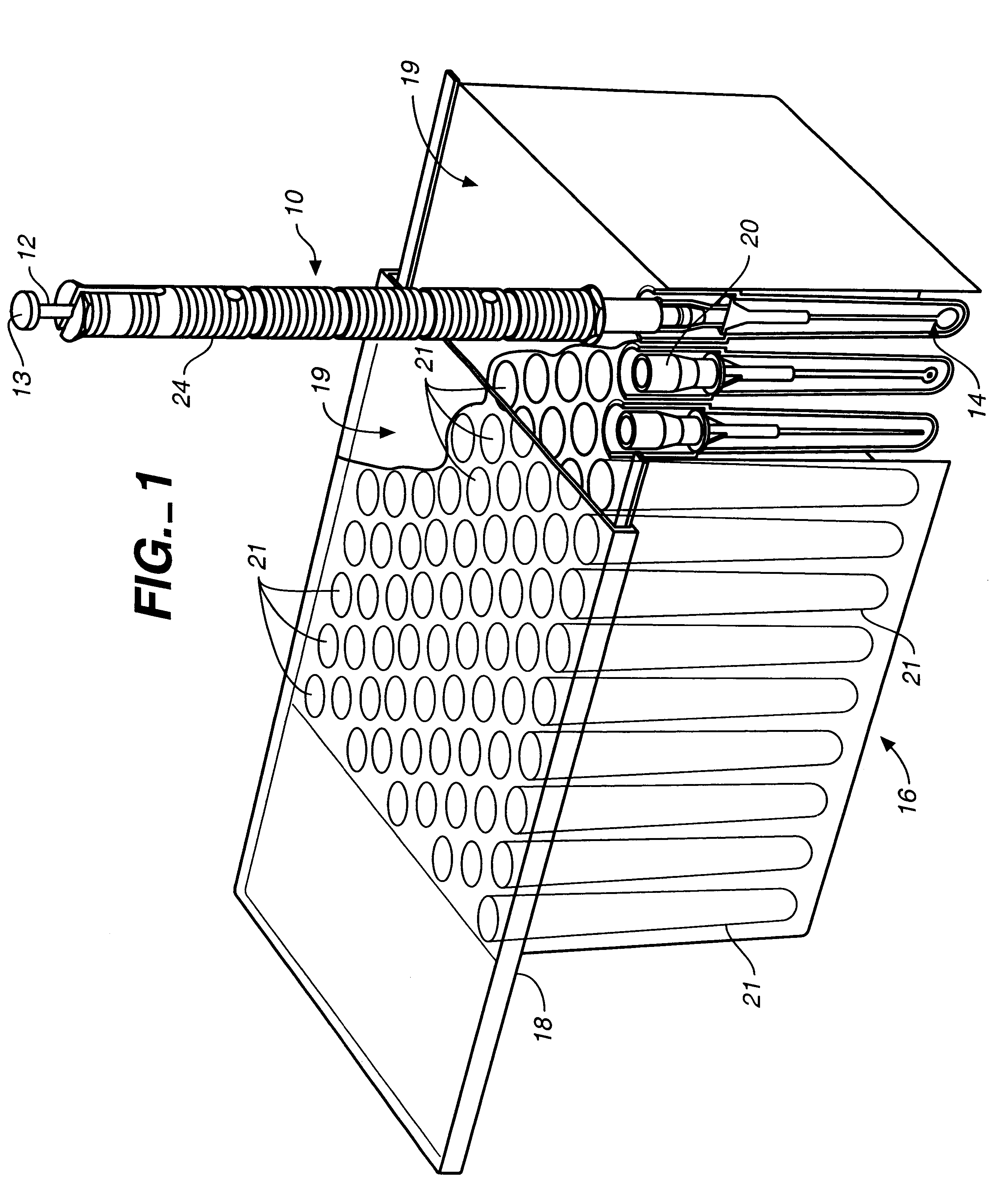
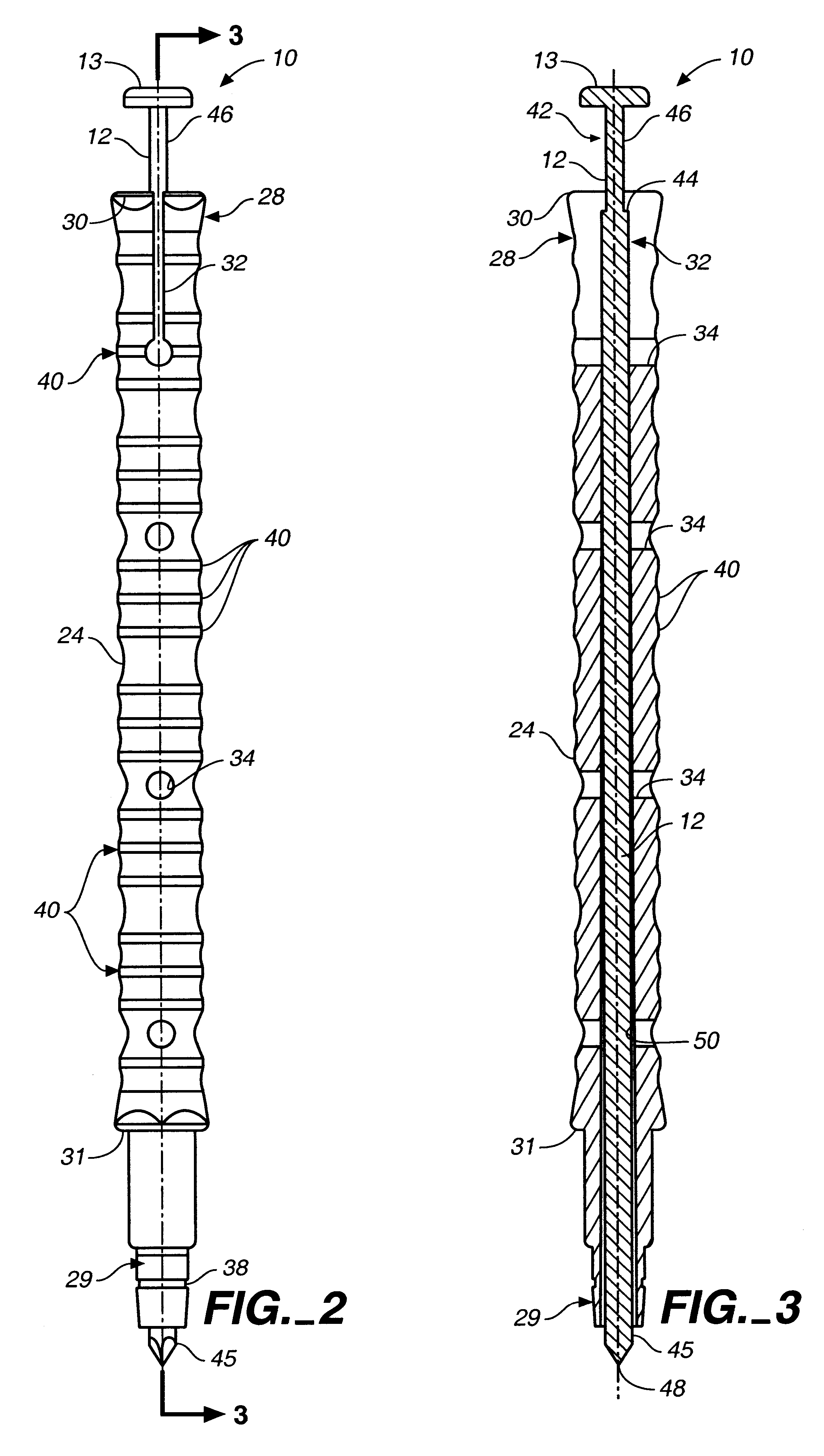
Briefly described, the inoculation loop assembly of the present invention is formed as a two-piece assembly, which reduces the molding cost and greatly simplifies assembly. The device comprises an elongated body having an upper end and a lower end and an axial bore therethrough, and an elongated plunger mounted for longitudinal movement within the axial bore of the body between an extended position and a retracted position. The plunger includes an upper end extending exteriorly of the upper end of the body with a finger pad thereon. The plunger further includes a plunger shoulder spaced from the finger pad along the length of the plunger, which cooperates with a body shoulder to limit plunger movement. The body includes a resilient, slotted upper end formed for outward displacement of the adjacent body portions to permit enlargement of the axial bore at the upper end of the body for insertion of the lower end of the plunger into the axial bore and advancement of the plunger in the bore to its normal operating range. A narrow diameter length of the plunger provides a plunger shoulder for engaging the body shoulder to limit movement of the plunger outwardly beyond its retracted position. The finger pad of the plunger is adapted to engage the upper end of the body to limit inward movement of the plunger beyond its extended position.
According to an aspect of the invention, the plunger is a one piece monolithically formed member and the body is a one piece monolithically formed member. Monolithic formation of the two-piece assembly reduces manufacturing and assembly costs while still retaining reliable loop mounting, manipulation, and ejection.
According to still another aspect of the invention, the body includes at least one radial hole extending through the body to the axial bore thereof Preferably, a plurality of radial holes are provided, each extending through the body to the axial bore thereof, and the plurality of radial holes are equally spaced along the length of the body in order to promote even and rapid cooling of the body mass after injection molding and after autoclaving.

Problems solved by technology

Typical prior art handles have been undesirably complex and costly to fabricate, requiring a multiplicity of injection molded and metal parts to fabricate and an undesirable amount of time to assemble.

Method used


Image

  • Handle for inoculating loop
  • Handle for inoculating loop
  • Handle for inoculating loop

Examples


Embodiment Construction

Reference will now be made in detail to the preferred embodiment of the invention, examples of which are illustrated in the accompanying drawings. While the invention will be described in conjunction with the preferred embodiment, it will be understood that the described embodiment is not intended to limit the invention specifically to those embodiments. On the contrary, the invention is intended to cover alternatives, modifications and equivalents, which may be included within the spirit and scope of the invention as defined by the appended claims.

Referring to FIG. 1, the improved inoculation loop handle of the present invention is designated generally by reference numeral 10. As described in more detail herein, handle 10 is a two-piece assembly comprising an elongated generally cylindrical body 24 with an axial bore therein for receipt of an elongated plunger 12 having a transversely extending finger pad 13 at its upper end. Plunger 12 is longitudinally movable within the axial bo...


PUM


Abstract

A two-piece handle assembly (10, 10a) including a plunger (12, 12a) and a body (24, 24a) having an axial bore (50, 50a) in which plunger (12, 12a) can move between retracted and extended positions. The upper end (28) of body (24, 24a) includes a pair of opposed longitudinal slots (32) that permit radially outward resilient movement of the upper end (28) to enlarge a bore (52), defined by a neck portion (54) of the body, to permit insertion of plunger (12) into body (24, 24a). A plunger shoulder (44) is designed to engage a body shoulder (55) to limit movement of the plunger in the direction of retraction, and a finger pad (13) is provided to limit movement of the plunger in the direction of extension.

Description

The present invention relates to inoculation devices and, more particularly, to a handle apparatus for sanitary manipulation and control of inoculation loops during inoculation procedures.In traditional laboratory inoculation techniques, as discussed in prior U.S. Pat. No. 5,330,899, entitled "Calibrated Inoculation Assembly and Method of Preserving Sterility," after a desired microorganism has been successfully incubated in a nutrient broth substance, it is necessary to further colonize the microorganism so that a particular strain can be identified and researched. For this, a predetermined quantity of inoculant from the broth is extracted and implanted in a nutrient medium so that the microorganism can be grown under controlled conditions.A common tool used to inoculate the nutrient medium is an inoculation loop, which includes a loop end that carries the inoculant solution to the nutrient medium. A handle device is releasably coupled to the opposite end of the inoculation loop in...

Claims


Application Information

Patent Timeline
IPC IPC(8): C12M1/26
CPCC12M1/262C12M33/02
Inventor DE VAUGHN, DONALD H.OTT, WOLFGANG
Owner BIO PLAS
Learn More