
Flat coreless vibrator motor using magnetic latching power

Inactive Publication Date: 2001-06-12
TOKYO PARTS IND CO LTD
View PDF4 Cites 23 Cited by
  • Summary
  • Abstract
  • Description
  • Claims
  • Application Information

AI Technical Summary

Benefits of technology

To solve the above problem, it is an object of the present invention to provide a flat coreless vibrator motor capable of holding a rotor in a specific position so as to effectively obtain a magnetic flux from a magnet by magnetic latching power, increasing vibration by increasing the amount of eccentricity of the center of gravity of the rotor, improving the mobility of the rotor since the adjacent segments of a commutator are not shorted, and whose manufacturing expenses are cut down by reducing the number of coils or the available sectional area of a magnet.
It is possible to improve the mobility of the eccentric rotor since the eccentric rotor is held in a specific position when it stops and to prevent the adjacent segments from being shorted by the protrusion.

Problems solved by technology

However, it costs much to manufacture the flat coreless vibrator motor of the three coil type since there are three coils.

Method used


Image

  • Flat coreless vibrator motor using magnetic latching power
  • Flat coreless vibrator motor using magnetic latching power
  • Flat coreless vibrator motor using magnetic latching power

Examples


Embodiment Construction

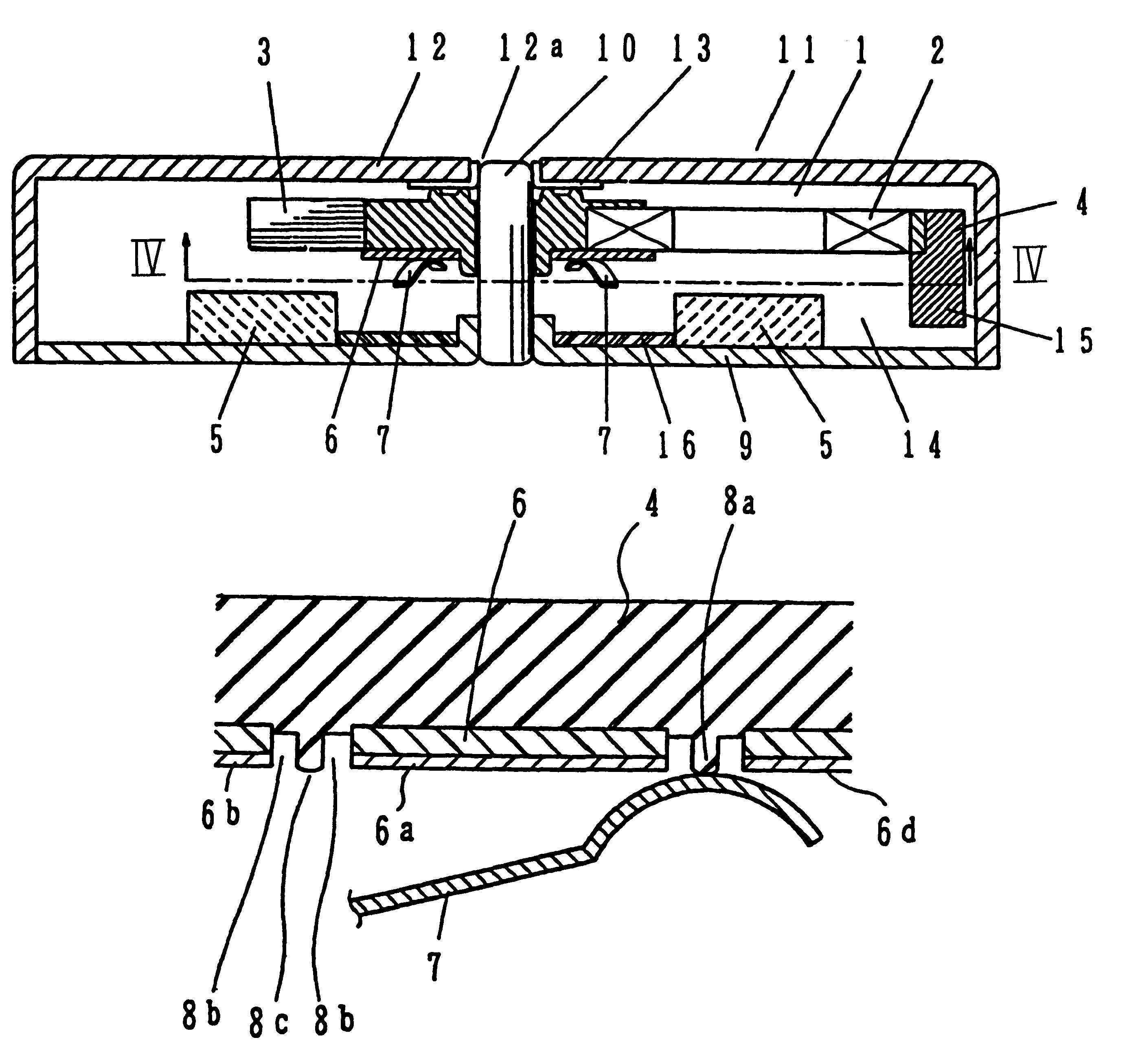
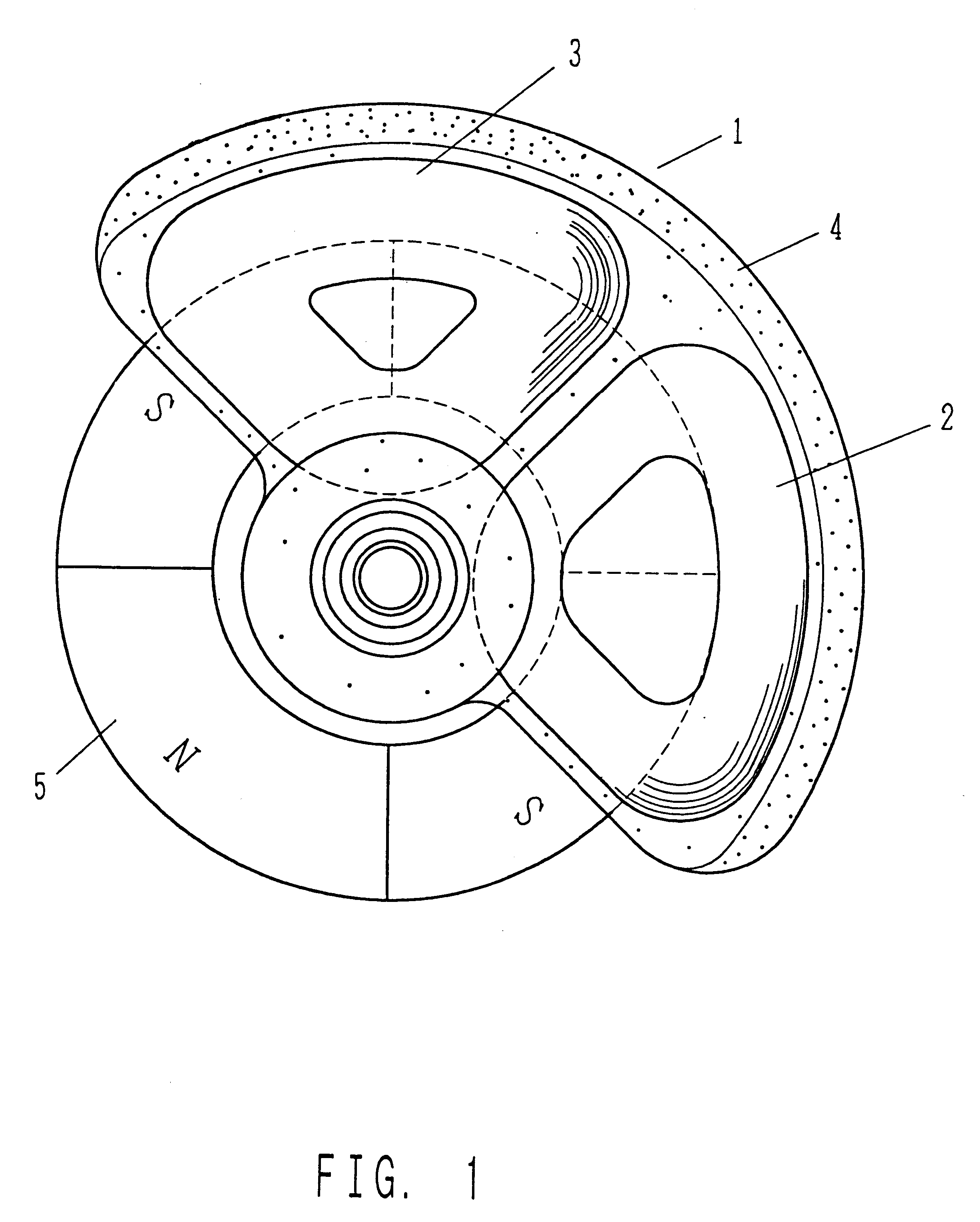
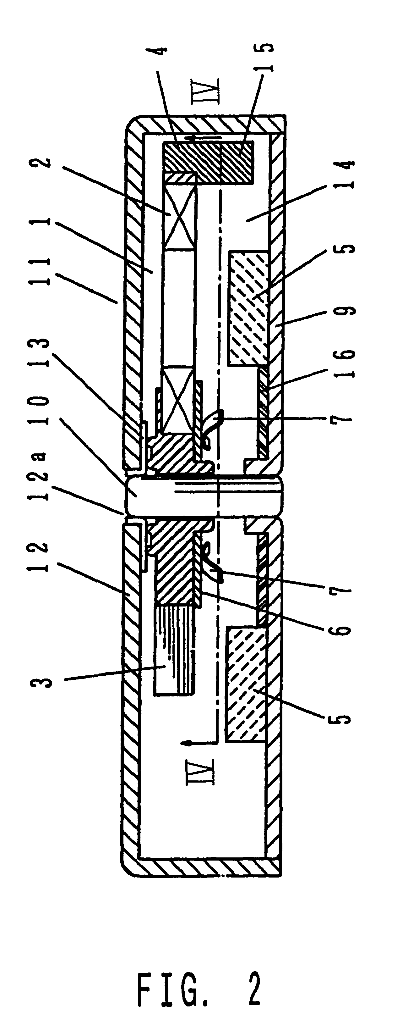
In FIGS. 1 through 4, an eccentric rotor 1 is integrally formed of a high density, slippery synthetic resin 4, with two coreless armature coils 2 and 3 tilted to one side. One having the two coreless armature coils is the coreless armature coil 2 formed by winding magnetic plated wire of a very thin plating. The coreless armature coil 2 formed by winding the magnetic plated wire has a relatively larger winding axis (namely, the diameter of a through hole in the coil is made larger) and a smaller number of windings than the other coreless armature coil 3 in order to prevent the generation of large magnetic attractive power. A magnet 5 of a disk-shape having a central hole, which faces the eccentric rotor 1, is magnetized so that it has alternate north and south poles N and S and is divided uniformly by four. The width of the magnet 5 is almost equal to the width of the through hole in the coreless armature coil 2. The position of the outer periphery of the magnet 5 coincides with the...


PUM


Abstract

A flat coreless vibrator motor holds a rotor in a specific position by magnetic flux from a magnet, increasing vibration by increasing the eccentricity of the center of gravity of the rotor, easily moving since the adjacent segments of a commutator are not short-circuited, and having reduced manufacturing costs. In the flat coreless vibrator motor, a four-pole magnet which has alternate north and south poles for providing a magnetic field to an eccentric rotor faces the eccentric rotor, in one side of which at least one coreless coil is located and in which a commutator having four segments, each diametrically-opposite pair of which are short-circuited, is installed. The flat coreless vibrator motor includes a unit for holding the at least one coreless coil of the eccentric rotor so that available conductor portions are at a specific position when the eccentric rotor stops, using the magnetic power of the magnet, a pair of brushes for supplying power to the eccentric rotor through the commutator in a position where the angle formed by the commutator and the brushes is 90.degree., and a protrusion arranged between the segments of the commutator coplanar with surfaces of the segments so that the adjacent segments are not short-circuited by the brushes and the brushes do not touch the protrusion.

Description

BACKGROUND OF THE INVENTION1. Field of the InventionThe present invention relates to a flat coreless vibrator motor using magnetic latching power suitable for use as a silent alert source for a small, portable communication device such as a radio pager or a portable telephone or a vibration source for a massager.2. Description of the Related ArtA conventional flat coreless vibrator motor is disclosed in U.S. Pat. No. 5,036,239.The flat coreless vibrator motor where a number of, for example, three armature coils 99 are eccentrically arranged is popular in the market since it is possible to control the amount of eccentricity of the center of gravity of a rotor to be large. However, it costs much to manufacture the flat coreless vibrator motor of the three coil type since there are three coils. Also, as shown in U.S. Pat. No. 5,036,239, in the flat coreless vibrator motor of the three coil type, all the coils contribute to the production of torque during a rotation for only an extremel...

Claims


Application Information

Patent Timeline
IPC IPC(8): H02K3/28H02K7/06H01R39/00H02K3/46H02K3/47H01R39/06H01R39/24H02K5/14H02K13/04
CPCH01R39/06H01R39/24H02K3/28H02K3/47H02K7/06H02K5/145H02K13/04
Inventor YAMAGUCHI, TADAO
Owner TOKYO PARTS IND CO LTD
Features
  • Generate Ideas
  • Intellectual Property
  • Life Sciences
  • Materials
  • Tech Scout
  • Unparalleled Data Quality
  • Higher Quality Content
  • 60% Fewer Hallucinations
Learn More