Reduced thickness of a light transmissive layer for a high density optical disc
Inactive Publication Date: 2001-06-12
SONY CORP
View PDF8 Cites 213 Cited by
Summary
Abstract
Description
Claims
Application Information
AI Technical Summary
This helps you quickly interpret patents by identifying the three key elements:
Problems solved by technology
Method used
Benefits of technology
Benefits of technology
Accordingly, an optical recording medium has been provided which achieves a storage recording capacity of at least 8 GB or more with excellent signal characteristics.
Problems solved by technology
However, optical recording mediums currently available do not have storage capacities of 8 GB or more.
Specifically, the tilt angle is easily affected by optical aberrations resulting from the thickness of the base of the optical recording medium.
Method used
Image
Click on the blue label to locate the original text in one second.
Reading with bidirectional positioning of images and text.
Examples
second embodiment
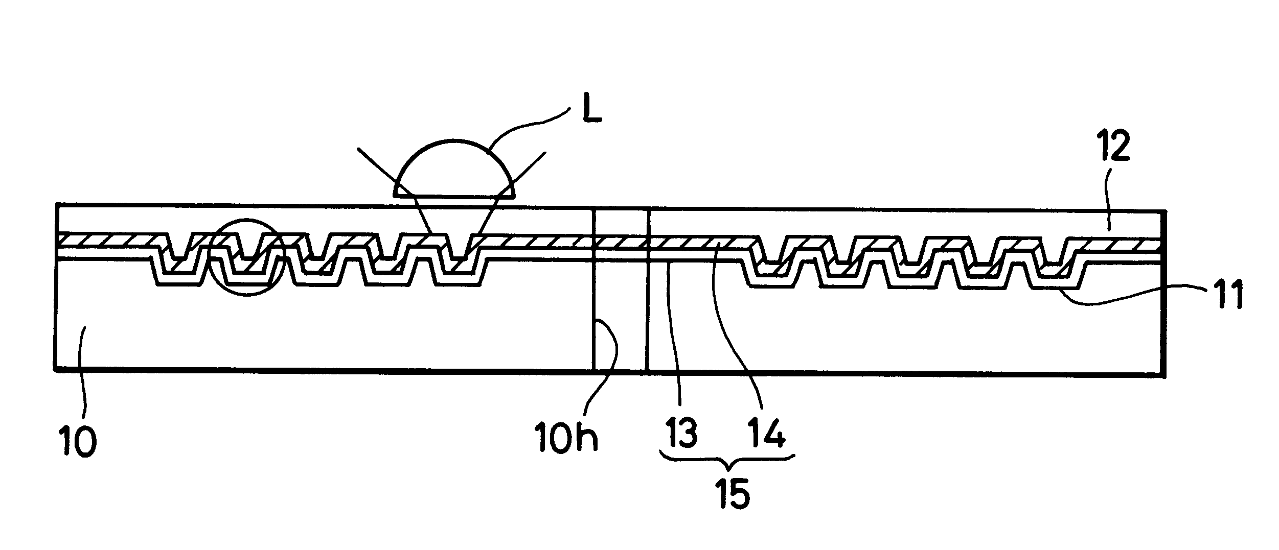
The light transmissive layer 12 can be formed by coating a liquid ultraviolet curing resin on the organic dye recording layer 14, drawing the resin, and then curing the resin by irradiation of light. FIG. 5 illustrates an optical recording medium according to the present invention wherein the light transmissive layer 12 can be formed by laminating a light transmissive film 17 having a uniform thickness on a liquid ultraviolet curing resin 16.
In this case, unevenness of the thickness of the light transmissive layer 12 is formed of the light transmissive film 17 and the bonded liquid ultraviolet curing resin 16 can be significantly reduced to 10 .mu.m by placing the light transmissive film 17 having the same diameter as that of the substrate 10 on the substrate 10 through the ultraviolet curing resin 16. The ultraviolet curing resin 16 is then spin coated thereon with the light transmissive film 17 being employed as a weight for the ultraviolet curing resin 16.
In the past, when an org...
third embodiment
FIG. 6 illustrates an optical recording medium according to the present invention wherein a transparent protective layer 18 is formed between the organic dye recording layer 14 and the light transmissive layer 12 in order to prevent the organic dye from being dissolved in the ultraviolet curing resin. This transparent layer 18 is formed of a simple substance or a mixture of an oxide, a nitride, sulfide, fluoride, etc., such as Mg, Al, Si, Ti, Zn, Ga, Ge, Zr, In, Sn, Sb, Ba, Hf, Ta, and of rare-earth elements, such as Sc and Y.
Since a total amount of light refraction at the light transmissive layer 12 and the transparent protective layer 18 must be constant, it is desirable that the thickness of the light transmissive layer 12 satisfies the equation 10-[(1.53d / n)] to 177-[(1.53d) / n] [.mu.m] assuming that the refractivity of the transparent protective layer 18 is n, its film thickness is d and the refractivity of the light transmissive layer 12 is 1.53.
As aforedescribed, the light tra...
fourth embodiment
The present invention also pertains to a multilayer optical recording medium having a plurality of information recording layers each of which is formed of a reflective film and an organic dye recording layer which are laminated on a guide groove. FIG. 7 illustrates an optical recording medium according to the present invention having such a multilayer optical recording medium. This multilayer optical recording medium includes a multilayer optical recording medium having a second information recording layer 15b formed on a first information recording layer 15a which is formed by injection molding of the substrate 10 and separated therefrom by an intermediate layer 19.
PUM
Abstract
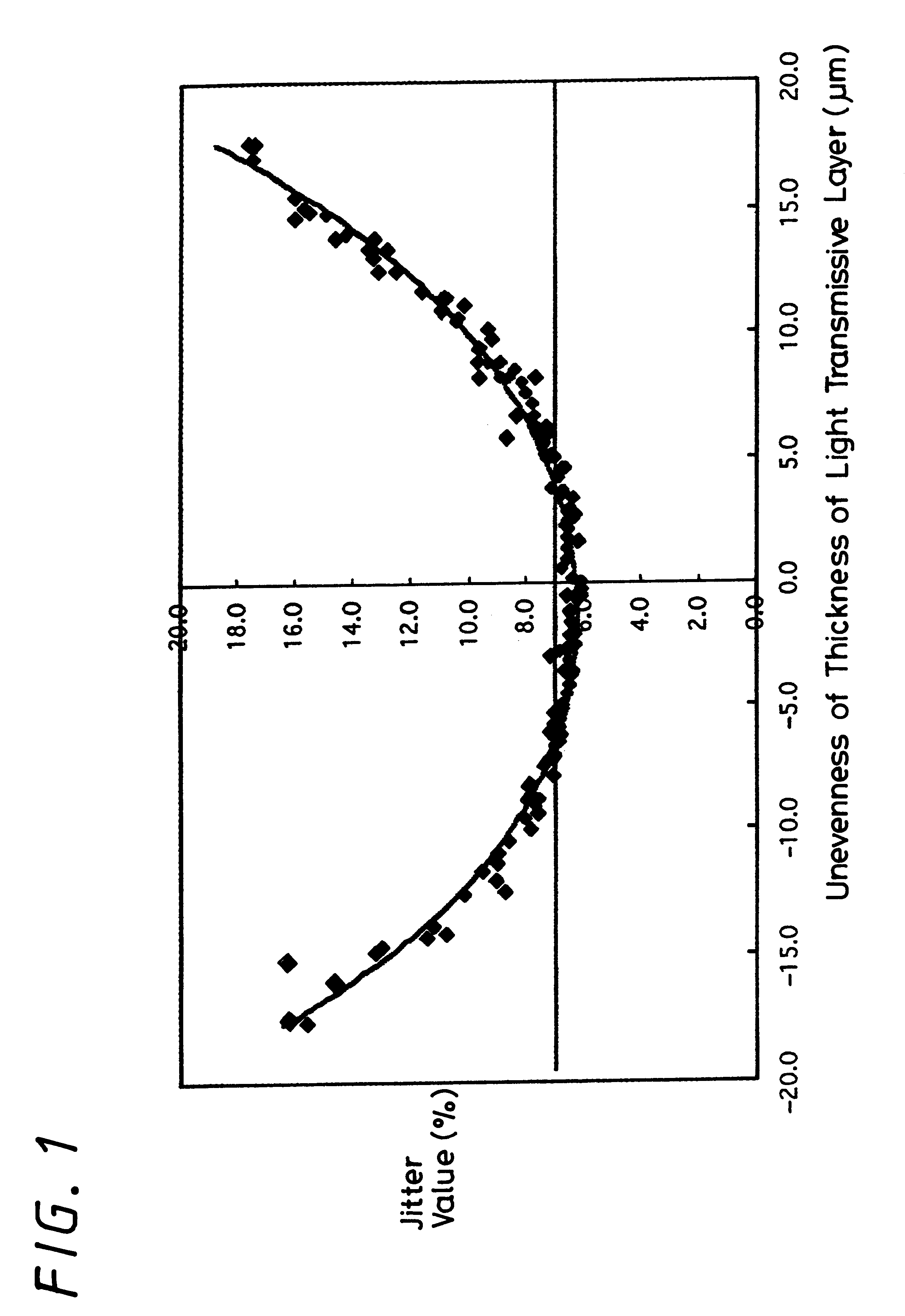
An optical recording medium is provided which achieves a higher recording capacity. This optical recording medium includes a base formed of thermoplastic resin which has a thickness ranging from between approximately 0.3 to 1.2 mm, a guide groove formed on the base, an information recording layer formed at least of a reflective film and an organic dyerecording layer provided on the guide groove, and a light transmissive layer having a thickness ranging from between approximately 3 to 177 mum. In this optical recording medium, the unevenness DELTAt of the thickness of the light transmissive layer is set within the range of:wherein N.A. represents a numerical aperture of an optical head device of the optical disk recording and / or reproducing apparatus and lambd represents the wavelength of laser light utilized by the optical disk recording and / or reproducing apparatus.
Description
The present invention relates to an optical recording medium having a guide groove, a reflective film, an organic dyerecording layer, and a light transmissive layer where information is read therefrom or recorded thereon by irradiation of light. More particularly, the present invention relates to an optical recording medium which can achieve a higher storage capacity by determining the relationship between the thickness of the light transmissive layer, the thickness unevenness of the light transmissive layer, and the skew margin (bend or warp). The present invention further relates to an optical disk apparatus for recording and / or reproducing the optical recording medium described herein.An optical recording medium capable of recording and / or reproducing NTSCsignal data of up to four hours on one side thereof has been proposed for optical disks of the next generation. This proposed optical recording medium thereby allows a home-use video disk recorder to record and reproduce data ...
Claims
Application Information
Patent Timeline
Application Date:The date an application was filed.
Publication Date:The date a patent or application was officially published.
First Publication Date:The earliest publication date of a patent with the same application number.
Issue Date:Publication date of the patent grant document.
PCT Entry Date:The Entry date of PCT National Phase.
Estimated Expiry Date:The statutory expiry date of a patent right according to the Patent Law, and it is the longest term of protection that the patent right can achieve without the termination of the patent right due to other reasons(Term extension factor has been taken into account ).
Invalid Date:Actual expiry date is based on effective date or publication date of legal transaction data of invalid patent.

