Computer fan speed control system
a technology of speed control system and fan, which is applied in the field of computer equipment, can solve the problems of reducing the longevity of electronic components, reducing the speed of operation, prolonging the longevity of the fan, etc., and achieves the effects of increasing the cooling capacity, increasing the speed of rotation, and increasing the voltag
Inactive Publication Date: 2001-06-19
ROUND ROCK RES LLC
View PDF130 Cites 91 Cited by
- Summary
- Abstract
- Description
- Claims
- Application Information
AI Technical Summary
Benefits of technology
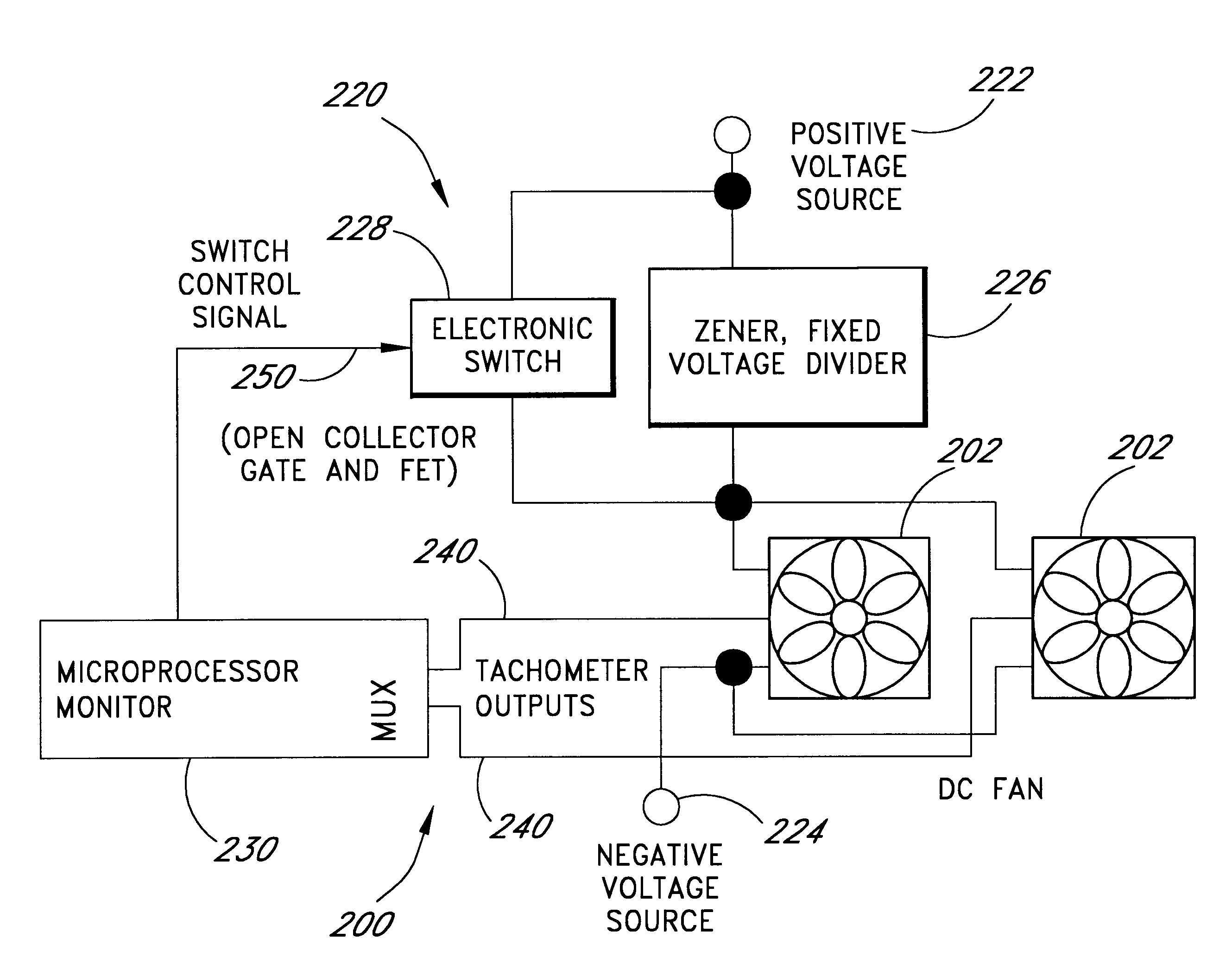
In another aspect of the invention, a cooling system for a computer is provided which comprises a plurality of fans adapted to provide forced-air cooling of a computer where each of the plurality of fans operates at a speed that is related to the voltage that is applied to the fans, a voltage source that provides a first voltage, at least one zener diode voltage divider connected to the voltage source and the plurality of fans so as to be interposed between the plurality of fans and the voltage source, at least one switch connected to the voltage source and the plurality of fans so as to be interposed between the plurality of fans and the voltage source, so that when the switch is in a first position, the plurality of fans receives a first input voltage and operates at a normal speed and so that when the switch is in a second position the plurality of fans receives a second input voltage and operates at a higher speed of operation which is more than the normal speed of operation, a speed monitoring system which provides an indication of the speed of operation of a plurality of fans, and a controller that receives signals from the speed monitoring system and ascertains that at least one of the plurality of fans is operating at an undesired speed of operation and, upon ascertaining that at least one of the plurality of fans is operating at an undesired speed of operation, induces the switch to move to a second position so that at least one of the remaining fans in the plurality of fans operates at a higher speed of operation wherein the controller, upon determining that at least one of the fans is not operating at a desired speed of operation, creates a record indicating that the at least one fan is not operating at the desired speed and wherein the controller upon subsequently determining that the at least one fan operating at the undesired speed is operating at a desired speed, induces the switch into a first position thereby reducing the speed of operation of at least one of the remaining fans to the normal speed.
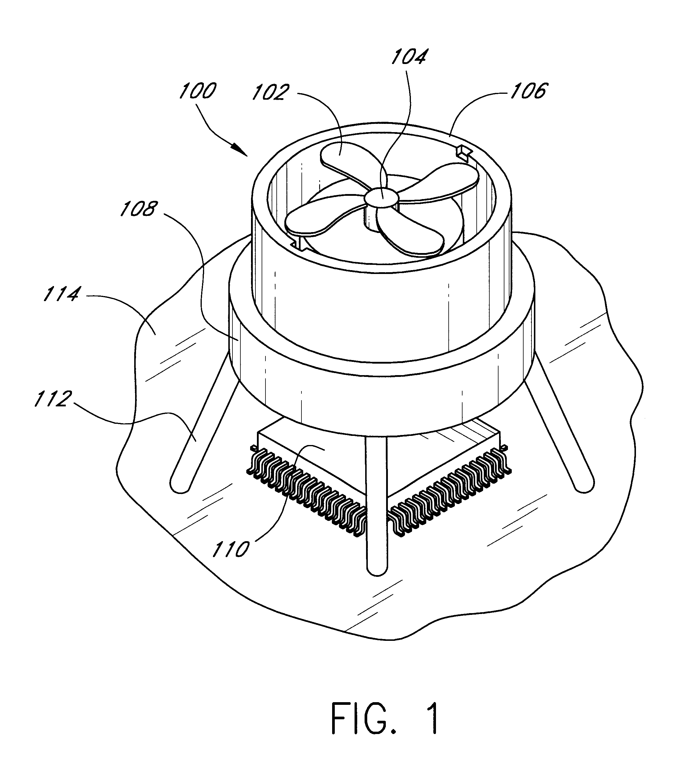
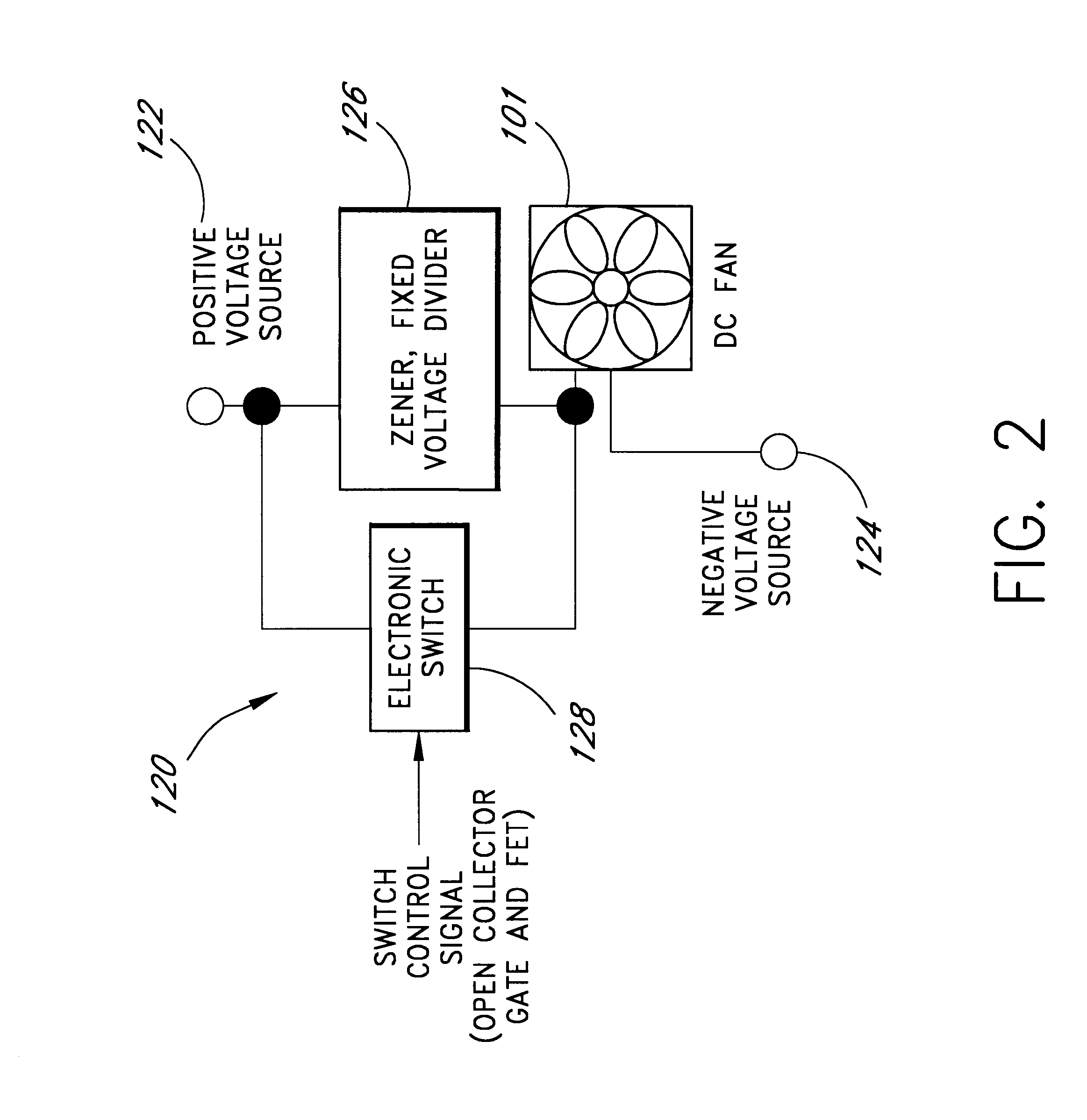
Hence, the foregoing description has described several embodiments of a circuit for controlling the operation of fan which incorporates a zener diode divider that can be selectively switched into series with the power input of a fan to decrease the voltage that is provided to the fan. This allows the fan to operate at a lower speed thereby prolonging the longevity of the fan and also decreasing the noise produced by the fan. In another embodiment, a cooling system is provided which incorporates the zener diode control circuit and a plurality of fans. The cooling system may also include a microprocessor that senses the speed of operation of the plurality of fans and, upon sensing that one or more fans are no longer operating at a desired speed, the microprocessor closes a switch to short out the zener bridge divider so that the remaining fans receive a higher voltage to offset the loss of cooling capacity resulting from the loss of the fan.
Problems solved by technology
Specifically, as personal computers have become increasingly sophisticated, these computers are using increased numbers of electronic components each of which produce greater amounts of heat.
This heat can result in damage to components within the chassis or casing of the personal computer or can also result in a decrease in the longevity of the electronic components.
Slower speed of operation prolongs the longevity of the fan and also decreases the noise generated by the personal computer.
At high speed operation, the noise generated by these fans would be distracting to the computer user.
This redundancy, however, increases the overall cost of the computer as more fans are installed than are actually needed for normal cooling operations.
Further, it will be appreciated that when all of the fans are operating, the fans are generating an increased amount of noise.
Unfortunately, these multi-speed fans are more expensive and increase the overall cost of the personal computer.
In the highly competitive market of personal computers, a small increase in the component cost can result in a significant effect on the overall profitability of the sale of the personal computer.
Moreover, while multi-speed fans are currently available for use with personal computers, if one of these fans fail, the prior art personal computers are often unable to detect the failure and to take corrective action.
While multi-speed fans can be used to provide varying cooling capacity within the personal computer chassis, these systems are not generally capable of accommodating a failure of one or more of the fans.
This of course causes greater power drain on the power supply, results in noisier computers and also decreases the longevity of the fans themselves.
Method used
View moreImage
Smart ImageViewing Examples
Examples
Embodiment Construction
Incorporation by Reference of Commonly Owned Applications
The following patent applications, commonly owned and filed on the same day as the present application are hereby incorporated herein in their entirety by reference thereto:
Login to View More PUM
 Abstract
A cooling system for cooling components of a computer is provided. The cooling system includes a DC fan which operates at a speed which is substantially proportional to the voltage that is applied to the fan. A zener diode voltage divider is connected in series between a voltage source and a first input of the fan. The second input of the fan is connected to a reference voltage source. A switch is also connected in series between the voltage source and the first voltage input of the fan so as to be connected in parallel with the zener diode voltage divider. When the switch is in a first position, the voltage produced by the voltage source is applied directly to the fan allowing the fan to operate at a first speed. When the switch is in a second position, the voltage from the voltage source is applied to the first input of the fan through the zener diode such that the first input of the fan receives a second voltage that is less than the first voltage thereby causing the fan to operate at a second speed. The zener diode voltage divider is substantially current independent such that the voltage drop across the zener diode is substantially independent of the current that is drawn by the fan.
Description
The subject matter of U.S. patent application Ser. No. 08 / 914,262 entitled "COMPUTER FAN SPEED CONTROL SYSTEM METHOD," and having attorney Docket No. MNFRAME.035A is related to this application.APPENDICESAppendix A, which forms a part of this disclosure, is a list of commonly owned copending U.S. patent applications. Each one of the applications listed in Appendix A is hereby incorporated herein in its entirety by reference thereto.COPYRIGHT RIGHTSA portion of the disclosure of this patent document contains material which is subject to copyright protection. The copyright owner has no objection to the facsimile reproduction by anyone of the patent document or the patent disclosure, as it appears in the Patent and Trademark Office patent files or records, but otherwise reserves all copyright rights whatsoever.1. Field of the InventionThe invention relates to computer equipment and, in particular, relates to a system and a method for sensing and controlling the speed of one or more coo...
Claims
Login to View More Application Information
Patent Timeline
 Patent Type & Authority Patents(United States)
IPC IPC(8): G06F11/07G06F1/20G06F1/26G06F9/445G06F11/32G06F11/30G06F11/34G06F13/40G06F21/00H04L12/56H04L12/24H04L12/40H04L12/12H04L12/26H05K7/20G06F1/00G06F3/06
CPCG06F11/3058G06F11/3072G06F11/3093G06F11/328G06F11/3466G06F13/4027G06F21/305H04L12/12H05K7/20209G06F1/20G06F1/206G06F1/26G06F9/4411G06F11/0748G06F11/0772F04D25/166F04D27/004G06F11/0793G06F2003/0692G06F2201/86Y02B60/34G06F3/0601G06F3/0673Y02B30/70Y02D30/50
Inventor HENDERSON, MICHAEL G.NGUYEN, KENJOHNSON, KARL S.
Owner ROUND ROCK RES LLC
Features
- R&D
- Intellectual Property
- Life Sciences
- Materials
- Tech Scout
- Unparalleled Data Quality
- Higher Quality Content
- 60% Fewer Hallucinations
Learn More Browse by: Latest US Patents, China's latest patents, Technical Efficacy Thesaurus, Application Domain, Technology Topic, Popular Technical Reports.
© 2025 PatSnap. All rights reserved.Legal|Privacy policy|Modern Slavery Act Transparency Statement|Sitemap|About US| Contact US: help@patsnap.com


