Temperature-dependent switch having a current transfer member

Inactive Publication Date: 2001-06-19
HOFSAESS MARCEL
View PDF26 Cites 35 Cited by
  • Summary
  • Abstract
  • Description
  • Claims
  • Application Information

AI Technical Summary

Problems solved by technology

Although the known switch meets many technical requirements, it nevertheless still exhibits disadvantages in certain applications.
One such disadvantage lies in the fact that after cooling, it automatically switches on again.
While a switching behavior of this kind may be entirely suitable for protecting, for example, a hair dryer, such is not the case with many applications, specifically those in which the device being protected must not automatically switch back on in order to prevent damage.
A disadvantage with the known switch, however, is the fact that the resistor and the bimetallic snap disk are housed in different chambers of an insulating housing, so that a separate metal bottom must be provided for heat transfer from the resistor to the bimetallic snap disk.
A further disadvantage lies in the fact that the contact bridge is pressed against the fixed contacts by a helical compression spring, whose force must be continuously overcome by the bimetallic snap disk in the open state.
The result of this heavy load on the bimetallic snap disk in the open

Method used


Image

  • Temperature-dependent switch having a current transfer member
  • Temperature-dependent switch having a current transfer member
  • Temperature-dependent switch having a current transfer member

Examples


Embodiment Construction

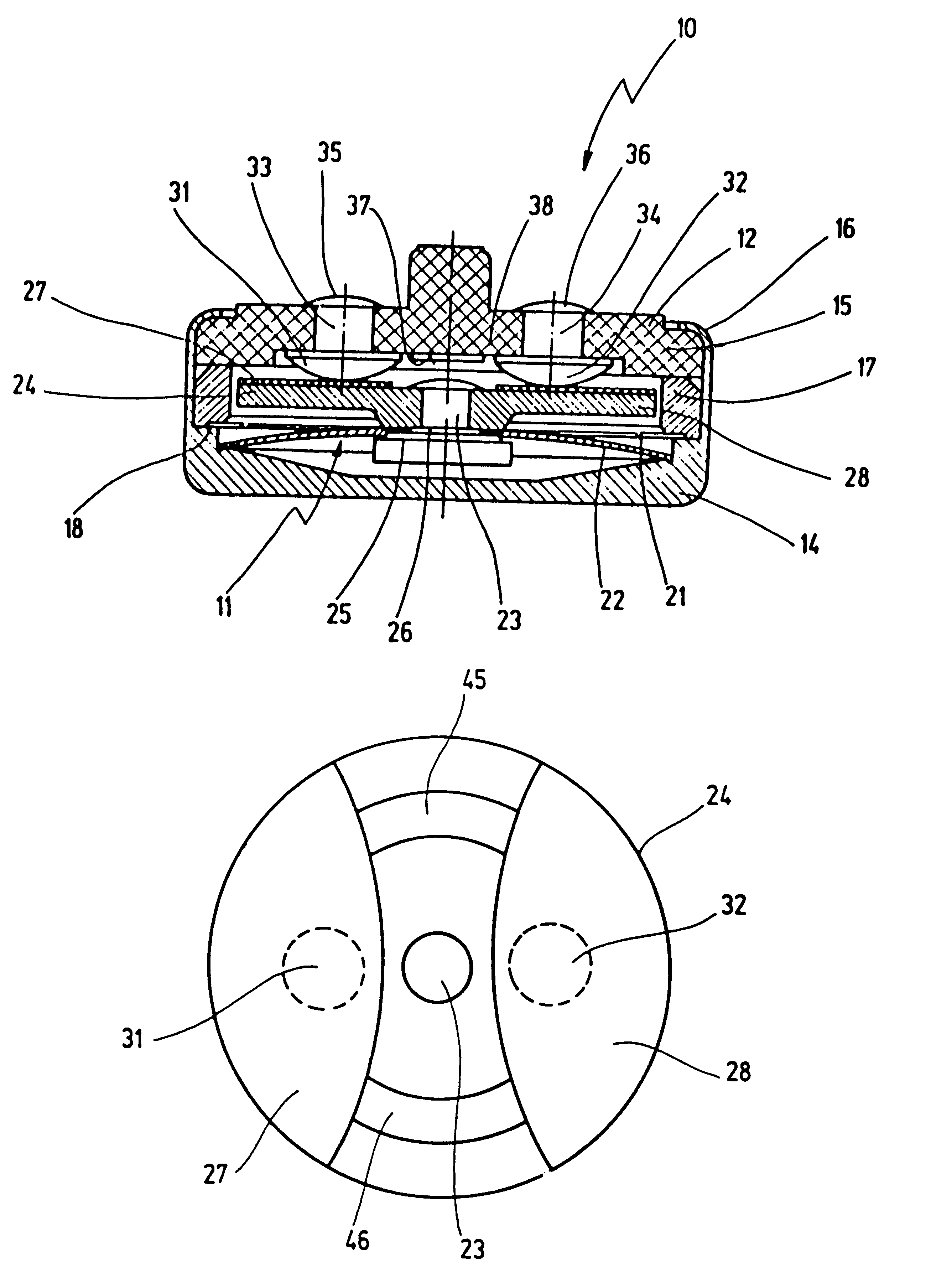
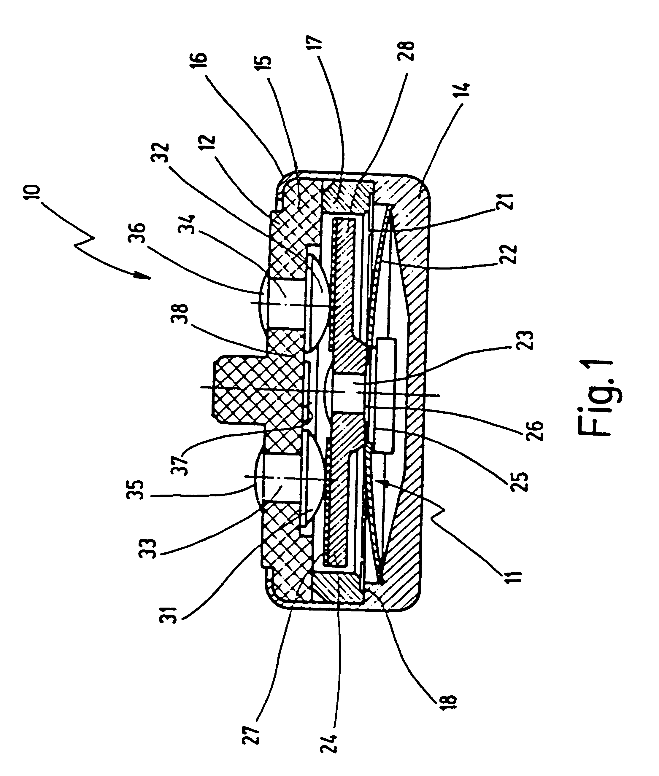
In FIG. 1, 10 designates a temperature-dependent switch which comprises a temperature-dependent switching mechanism 11 that is housed in a housing 12.

Housing 12 comprises a lower part 14 and an upper part 15, closing off said lower part, which upper part is held on the latter by a flanged-over rim 16 of lower part 14. Arranged between lower part 14 and upper part 15 is a ring 17 which is braced on a step 18 of lower part 14 and there guides a spring disk 21 of switching mechanism 11 at its rim.

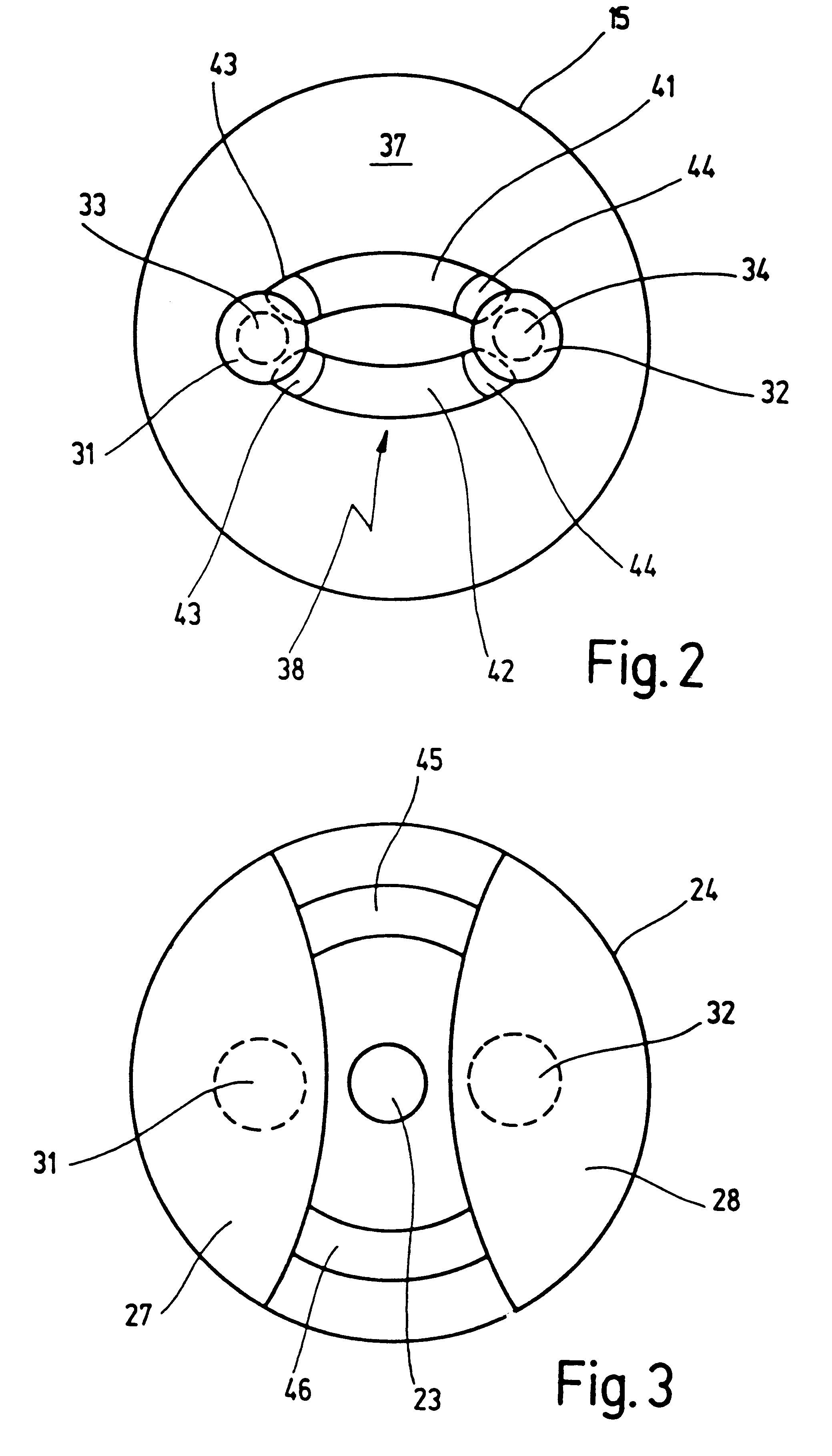
Switching mechanism 11 also comprises, in addition to spring disk 21, a bimetallic snap disk 22 which, together with spring disk 21, is penetrated centrally by a stem-like rivet 23 by way of which they are mechanically joined to a current transfer member in the form of a contact plate 24. Rivet 23 has a first step 25 on which the bimetallic snap disk sits with radial and axial clearance, a second step 26 being provided on which spring disk 21 sits, also with radial and axial clearance.

The afor...


PUM


Abstract

A temperature-dependent switch 10 has a temperature-dependent switching mechanism 11; a housing 12, receiving the switching mechanism 11 and having a lower part 14 and an upper part 15; and two stationary contacts 31, 32, provided on the upper part 15 on its inner side 37, each contact being connected to an associated external termina 35, 36. A current transfer member is arranged on the switching mechanism 11 and moved by it, which transfer member is in contact with the two stationary contacts 31, 32 in temperature-dependent fashion. There is arranged physically in the region of the current transfer member and upper part 15 at least one resistor 38 which is electrically connected between the stationary contacts 31, 32 at least when the current transfer member is in contact with them.

Description

1. Field of the InventionThe present invention relates to a temperature-dependent switch, having a temperature-dependent switching mechanism, a housing receiving the switching mechanism, which housing has a lower part and an upper part, two stationary contacts provided on the upper part on its inner side, each contact being connected to an associated external terminal, and a current transfer member, arranged on and moved by the switching mechanism, which current transfer member is in contact with the two stationary contacts in temperature-dependent fashion.2. Related Prior ArtA switch of this kind is known from DE 26 44 411 C2.The known switch has a housing with a cup-like lower part into which a temperature-dependent switching mechanism is placed. The lower part is closed off by an upper part which is held on the lower part by the latter's elevated rim. The lower part can be made of metal or of insulating material, while the upper part here is always made of insulating material.Two...

Claims


Application Information

Patent Timeline
IPC IPC(8): H01H1/00H01H37/00H01H1/50H01H37/54
CPCH01H1/504H01H37/5427
Inventor HOFSAESS, MARCEL
Owner HOFSAESS MARCEL
Why Eureka
Try Eureka