Downhole oil-sealed bearing pack assembly

a technology of oil-sealed bearings and assembly parts, which is applied in the direction of sealing, transportation and packaging, mechanical equipment, etc., can solve the problems of introducing the polished bearing elements to abrasive particles such as mud, grit and formation cuttings, and the rotational bearing assembly must endure severe vibration, shock and axial and radial loading, and achieve the effect of eliminating large differential pressur

Inactive Publication Date: 2001-06-26
BICO DRILLING TOOLS
View PDF34 Cites 69 Cited by
  • Summary
  • Abstract
  • Description
  • Claims
  • Application Information

AI Technical Summary

Benefits of technology

The oil-sealed bearing pack assembly of the present invention is intended for use in a variety of drill motor assemblies and various rotor and stator designs. The oil-sealed bearing pack assembly provides a non-contact flow restrictor device for eliminating large differential pressures across upper and lower seals of the bearing pack assembly. The non-contact flow restrictor includes an inner restrictive element attached to a rotatable drive shaft and an outer restrictive element secured to a stationary bearing housing. The inner restrictive element can include an outwardly extending ring adjacent to a first land and the outer restrictive element can include an inwardly extending ring adjacent to a second land. During rotation of the drive shaft the inwardly and outwardly extending rings remain a distance from the second and first lands, respectively, thus permitting a fluid to traverse the rings and lands. The non-contact flow restrictor device eliminates the large differential pressures which occur across upper and lower seals.
Additionally, the bearing pack assembly of the present invention includes a wear sleeve for handling the wear on the upper and lower seals. The wear sleeve also protects the drive shaft from unnecessary wear. The wear sleeve includes a groove cut into a hollow sleeve which is secured to the rotatable drive shaft. A thermally conductive fluid within the groove conducts heat generated by the seals from the wear sleeve to the shaft.
The bearing pack assembly of the present invention also provides a convenient means for determining the amount of oil remaining in the oil reservoir. A floating piston and dipstick assembly allows an operator to measure the remaining oil without having to disassemble the bearing pack assembly. The piston and dipstick assembly includes a chamber for containing oil and a drilling fluid. A floating piston applies pressure to the oil in the chamber and prevents the drilling fluid from mixing with the oil. A conduit extending into the chamber permits a dipstick to measure the location of the piston within the chamber to determine the amount of oil remaining within the chamber.

Problems solved by technology

As a result of this drilling method, the rotatable bearing assembly must endure severe vibration, shock, and axial and radial loading.
The rotation of the drive shaft within the bearing assembly creates a substantial amount of heat within the individual bearing elements.
Although this method of cooling was effective, it had the disadvantage of introducing the polished bearing elements to abrasive particles, such as mud, grit and formation cuttings.
The abrasive particles caused excessive wear on the bearings and reduced their effectiveness and life expectancy.
Another disadvantage with mud cooled or lubed thrust bearings was the necessity of spherical rolling elements, as opposed to cylindrical rolling elements, due to grit and debris in the mud.
A disadvantage with mud cooled thrust bearings with spherical rolling elements was that spherical rolling elements have a lower load capacity than cylindrical rolling elements.
Sealing this system, however, was difficult because the pressure of the drilling mud within the drill string and drill motor was often 2,000 pounds per square inch (psi) greater than the drilling mud pressure after exiting the nozzles of the drill bit.
Thus, the disadvantage of this system was that for the seals to protect the oil-filled bearing chamber from drilling mud, the seals needed to be able to seal the 2,000 psi differential across the seal.
As a result, the life expectancy of these seals was very low and failures occurred frequently.
Drilling mud would leak between the two contacting surfaces causing a gradual pressure drop from the high pressure of the drill string to the low pressure of the borehole annulus.
The disadvantage of this system included wear of the mating surfaces due to their sliding contact.
Another disadvantage was that the fluid which leaked across the mechanical face seal needed to be nonabrasive to minimize the erosion of the mating surfaces.
For example, since the drive shaft is often under severe bending and torsional loading conditions during operation, applying any type of coating to the drive shaft reduces the shaft's fatigue life and increases the probability of fatigue failure.
Another disadvantage of coating the drive shaft manifests itself when the coating becomes worn and the drive shaft must be taken out of service to be recoated.
During the period of time in which recoating occurs, another expensive drive shaft is required to put the apparatus back into operation.
Thus, an operator would need an inventory of expensive replacement drive shafts to drill with a coated drive shaft.
The disadvantage of this system was the excessive heat generated at the seal and wear sleeve interface which caused the seals to overheat and fail.
A disadvantage of the floating piston was its tendency to bind between the drive shaft and the bearing housing as the drive shaft bent in response to side loadings.
Another disadvantage included the roller bearing scarring the surface of the rotating drive shaft in the area which the seals contacted the drive shaft.
Yet another disadvantage of this system included the absence of a means for checking the oil level within the reservoir while out on a rig or platform.

Method used


Image

  • Downhole oil-sealed bearing pack assembly
  • Downhole oil-sealed bearing pack assembly
  • Downhole oil-sealed bearing pack assembly

Examples


Embodiment Construction

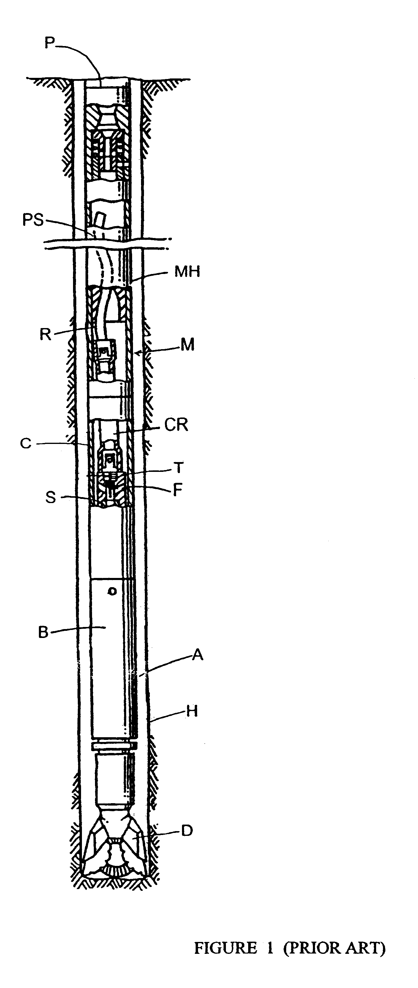
FIG. 1 shows a typical prior art downhole fluid motor M and drill assembly within a borehole H. During operation of the fluid motor M, drilling fluid or mud is circulated downwardly through a drill pipe string P through the power section PS into a connector rod housing C containing a connector rod CR. The connector rod housing C is secured to a relatively stationary motor housing MH and the connector rod CR is connected to a motor rotor R. The connector rod housing C is attached, often via a threaded connector, to an upper end of a bearing housing B. A rotatable hollow drive shaft S is secured within the bearing housing B. The drive shaft S extends downwardly through a lower end of the bearing housing B and connects to a drill bit D. At its upper end, the drive shaft S is attached to the connector rod CR by a drive shaft cap T.

The drive shaft cap T includes radial fluid passages F which provide fluid communication between the interior of the connector rod housing C and the bore of t...


PUM


Abstract

A downhole oil-sealed bearing pack assembly is provided for protecting bearing elements and seals. The bearing pack assembly includes a non-contact flow restrictor for reducing large differential pressures across sealing elements. The non-contact flow restrictor includes an inner restrictive element attached to a rotatable drive shaft and an outer restrictive element secured to a stationary bearing housing. The inner restrictive element can include an outwardly extending ring adjacent to a first land and the outer restrictive element can include an inwardly extending ring adjacent to a second land. During rotation of the drive shaft the inwardly and outwardly extending rings remain a distance from the second and first lands, respectively, thus permitting a fluid to traverse the rings and lands. The invention also provides a wear sleeve for increasing seal and shaft life. The wear sleeve includes a groove cut into a hollow sleeve which is secured to the rotatable driveshaft. A cooling fluid within the groove dissipates heat generated by seals contacting the wear sleeve on the rotating shaft. Further, a piston and dipstick assembly is provided for supplying oil to bearing elements and for measuring oil within a reservoir. The piston and dipstick assembly includes a chamber for containing oil and a drilling fluid. A floating piston applies pressure to the oil in the chamber and prevents the drilling fluid from mixing with the oil. A conduit extending into the chamber permits a dipstick to measure the location of the piston within the chamber to determine the amount of oil remaining within the chamber.

Description

1. Field of the InventionThe present invention relates generally to bearing assemblies for a drilling motor. In particular, the present invention relates to downhole oil-sealed bearing pack assemblies for a drilling motor.2. Description of the Related ArtIn the oil and gas industry, as well as in mining and other industries, holes are often drilled into the earth to reach the desired stratum to evacuate natural resources. To drill deep holes, the practice of using a fluid motor to drive a drill bit has become commonplace. In operation, the fluid motor is installed at the lower end of a drill pipe string and drilling fluid or mud is circulated down through the drill string and motor. The drilling mud flowing through the motor causes a mounted driveshaft to rotate. A drill bit, which contains nozzles, is secured to the end of the drive shaft and rotates to cut through the formation or stratum. Simultaneously, the drilling mud passes through the bit nozzles to flush away the cuttings. ...

Claims


Application Information

Patent Timeline
Patent Type & Authority Patents(United States)
IPC IPC(8): E21B4/00E21B4/02
CPCE21B4/003Y10S277/93
Inventor BESHOORY, EDWARD JOSEPH
Owner BICO DRILLING TOOLS
Why Eureka
Try Eureka